Maker Pro
Maker Pro

Lets go into my induction stove

Rui Almeida

Nov 3, 2016
23
Joined
Nov 3, 2016
Messages
23
Hi there!
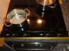
I have an induction stove. And it has been working excellently for 16 years!
Until the right side stopped working.

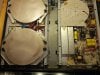
I really want to put this working again! Mostly because it's cheaper and more ecological. So I hope there is someone there that can help! (I upload image of the stove's inside.)

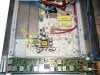
Opened it up and saw four burnt components (resistors R11 R12 and transistors Q3 Q4, see images) on the main PCB. Got those through the internet, substituted them and turned it back on. (The resistors I bought are green 48 Ohm 1W power and a bit larger)

Result:
Just my luck; the left side went dead
But the right side worked fine... for three days :-(
Opened it up and Q4 definitely seems to have AGAIN a burn mark!

Action:
Wait for your advise on how to proceed with the right side.
From comparison between the two identical PCBs I substituted on the left side the 68 kOhm R31 and R32 resistors(see image) as these seemed clearly to be off mark with a multimeter reading as compared to the color code and the left PCB board.

Result:
Right: on hold
Left: Back from the dead ... but zombie-like, because one plate works fine, the other plate works fine, but if I want to use both of them, then one just falls away (display starts to blink and after a while it disconnects, as if no pan was on it). It did this for some days, but today it decided to behave and work properly! How starnge is that!?

Any advice here is very welcome.
R.A.
 

Attachments

  • AEG 618K inside.jpg
    AEG 618K inside.jpg
    304.6 KB · Views: 289
  • BurntQ3Q4.jpg
    BurntQ3Q4.jpg
    201.2 KB · Views: 353
  • BurntR11R12.jpg
    BurntR11R12.jpg
    208.7 KB · Views: 254
  • BurntR31R32.jpg
    BurntR31R32.jpg
    374.8 KB · Views: 514

Rui Almeida

Nov 3, 2016
23
Joined
Nov 3, 2016
Messages
23
I found this image that might be of some assistance to someone willing to help.
 

Attachments

  • PCB technical layout.JPG
    PCB technical layout.JPG
    175.3 KB · Views: 951

73's de Edd

Aug 21, 2015
3,629
Joined
Aug 21, 2015
Messages
3,629
.


Sir Rui Almeida . . . . . . .

Firstly . . . . we can't initially quite perceive of whether dealing with a Maserati or a Lamborghini . . . .unless it might be a Fagor Brandt and being equipped with the 1X3 package .

Initial observation of R11 and R12 as being related to their associated companion parts, also reveals Q3 and Q4 as also being two cratered parts.

We need to get you to give us the full number of the ST branded controller IC located just under the marked jumper wire SF16.

Am I seeing 12 pushbuttons associated with the control board / display portion ?

Waiting for your fill in . . . . .


73's de Edd

.
 

Rui Almeida

Nov 3, 2016
23
Joined
Nov 3, 2016
Messages
23
Hi Mr 73's de Edd!
Thank you soo much for your reply.
As I understand it these power boards are in a lot of induction ovens, mine is a AEG model 618K. You are right, I in fact got the image from a Fagor Brandt pdf file.
Yes, the burnt resistors and transistors are directly connected although on oposite sides of the PCB board.
Here is the info on the ST IC chip: SG 3524 W990A9806 MALAYSIA
Now about the display I put here a photo. But I have for each side a timer for the power plate (bottom left and top right) and a step up and step down power button.
Whatever more information you need please ask, if there are some multimeter measurements I should make... I will.
Again thank you for your help.
 

Attachments

  • AEG 618K outside.jpg
    AEG 618K outside.jpg
    259.5 KB · Views: 118

Rui Almeida

Nov 3, 2016
23
Joined
Nov 3, 2016
Messages
23
Here's an update on having done nothing...
The left side of the stove went again into its zombie-like state: it cannot feed both induction plates at the same time.
I remember some days ago having checked the relays on the power board feeding them the 24VDC and hearing every time the click of the circuit closing, so I thought all was well, but could it be that the contacts are worn out and no current flows? How to check this, should I apply the 24VDC and read the ohmage across the 240VAC part? Is the problem actually with the relays, or could it be their driving mechanism?
 

Maxwell

Oct 1, 2016
47
Joined
Oct 1, 2016
Messages
47
Here's an update on having done nothing...
The left side of the stove went again into its zombie-like state: it cannot feed both induction plates at the same time.
I remember some days ago having checked the relays on the power board feeding them the 24VDC and hearing every time the click of the circuit closing, so I thought all was well, but could it be that the contacts are worn out and no current flows? How to check this, should I apply the 24VDC and read the ohmage across the 240VAC part? Is the problem actually with the relays, or could it be their driving mechanism?

Remove them and do a simply continuity on the contact?
 

Rui Almeida

Nov 3, 2016
23
Joined
Nov 3, 2016
Messages
23
Allright... thank you Maxwell. I'm away for the weekend but wil try this monday when I get back. Just a few questions: (i) can't I do this with the components in the circuit, I would feed the 24volts and read the ohms on the shorted circuit!? (ii) from what value of Ohms up will I have to concludentes that the relay(s) is the faulty component?
 

Maxwell

Oct 1, 2016
47
Joined
Oct 1, 2016
Messages
47
I would perform the following check to confirm the relays are ok:

- while in circuit, turn on the board, if you hear the click, take a VDC reading across the coils of the relay, this should be very close to 24vdc, if not, then you have an issue in the LV circuit.

- Take them out of circuit, desolder. Then while out of circuit, measure across the NC contact and confirm 0 Ohm reading, measure across NO contact and confirm infinite Ohm.

- Apply 24vdc across relay coils and measure across the NO contact to confirm 0 Ohm, measure across the NC contact to confirm infinite Ohm.

- While measuring NO contact, take away 24vdc source and confirm that the reading immediately goes from 0 Ohm to infinite (relay opening properly).
 
Last edited:

Rui Almeida

Nov 3, 2016
23
Joined
Nov 3, 2016
Messages
23
Thanks a million. Monday, perhaps tuesday (when I'm back home), I'll give feedback of the suggested procedures' results.
 

Rui Almeida

Nov 3, 2016
23
Joined
Nov 3, 2016
Messages
23
Hi Maxwell, I hooked up wires just to read on the relays, while in-circuit, the things you suggested, even the resistance (didn't therefore desolder the relays), here are the results:
(Note I wrote that the operating voltage for the relay was 24V but it is actually 12V, and this was what I did use before, sorry for the mistake)

OPERATING: Left-side - UP
left-Relay
low power: pos1,2,3,4,5,6(50Watt-400Watt), clicks hearded, voltage oscilates between 11.70 and 12.22V
high power: pos7,8,9,P(600Watt-2800Watt), no clicks hearded, voltage stable at 11.70V

Out of curiosity I measured the voltage on the right relay while operating just the left relay, while in low power, no voltage is read, but in high power and depending on the power, the voltage goes from 0.01V to 0,25V.

OPERATING: Left-side - DOWN
Right-Relay
low power: pos1,2,3,4,4*,5(50Watt-400Watt), clicks hearded, voltage oscilates between 11.90 and 12.30V
high power: pos5*,6,7,8,9,P(600Watt-2800Watt), no clicks hearded, voltage stable at 11.85V

Out of curiosity I measured the voltage on the left relay while operating just the right relay, while in low power, no voltage is read, but in high power and depending on the power, the voltage goes from 0.03V to 0,56V.

For both relays I had wires to measure the ohms for NO, and for when the circuit was closed (high-power-no-clicks), and the results are as expected, infinite ohms and close to zero respectively.

What is crazy o_O is that again today after doing these tests I was again able to use both left UP and DOWN zones at the same time!!?? This happened once before. This is going to drive me crazy!

Do you have any suggestion concerning the problem on the RIGHT zones, where the same transistor got again burnt?
 

Maxwell

Oct 1, 2016
47
Joined
Oct 1, 2016
Messages
47
Some fluctuation is normal, depending on the loads attached. If you want to explore this further, you could start by checking the capacitors on this board, specifically the low voltage ones to see if their capacitance and ESR is still in spec.

You could also try hammering the 12v circuit a bit by wiring in a few low power LED's to see if the voltage drops off or not.

The fried transistor looks like a darlington circuit, meaning the second transistor will be switching a lot more current than the first one in the circuit, are you sure it's up to spec? Might also help to know what this transistor is switching. The trace going to the solder points on pin 3 looks fairly beefy for such a tiny transistor, so i'm guessing it's switching quite a bit of current. Alternatively ofc the load it's switching might be pulling more current than it should, causing the transistor to pop frequently.

If anything you can rule out the relays as suspects, the LV circuit seems ok two, but confirm the capacitors, and confirm it's able to stay stable with bigger load (like two relays or some LED's in series).

I actually have quite a few of these PCB's lying around in my workshop, lol... they are found in almost ALL electrolux brand induction cookers... and they break like pretzels :p
 

Rui Almeida

Nov 3, 2016
23
Joined
Nov 3, 2016
Messages
23
Ok thanks Maxwell. About these low(12V) voltage capacitors, there are a few I think, I suppose I have to take them out of circuit one by one to check them, right? though none of them seem bulged ... also I suppose I will need to buy an ESR meter, perhaps it's cheaper to just substitute them right from the start!
About plugging in low power leds, where exactly would I put these, at the relay entries?

About the Q3 and Q4 seen in the figure above, I saw in another site that these components were 5Bp transistors with specs like these so I bought and substituted Bipolar Transistors - BJT Bipolar Transistors - BJT PNP/ 45V/ 500mA. So these components should not receive more than 500mA, I could check the voltage drop across the 'beefy' resistance in my next try with a new transistors. Also, are you saying that the power switching diodes D39 and D34 that follow may also be affected?

So I guess I have to shop for components (capacitors, transistors, power switches?...) ... I will wait for your advice before placing an order.

You know, I've been using this stove dayly for 16 years and it worked like a charm... till now.
When all fails, you may sell me one of those in your workshop :)
 

Rui Almeida

Nov 3, 2016
23
Joined
Nov 3, 2016
Messages
23
Update: having done nothing, the left zones now exhibit the following behaviour:
Left-UP: doesn't detect any pan, doesn't warm up, display keeps blinking until timeout shuts it off.
left-DOWN: works normally, though there is a strange behaviour; when I put the timer and it comes to zero and starts beeping it turns this zone off, as it should, but then the "hot zone" indication led, at some beeps, goes off while the "hot zone" indication led of zone Left-UP (?!) goes on. Very strange!
 

Maxwell

Oct 1, 2016
47
Joined
Oct 1, 2016
Messages
47
I don't think you want the ones from my workshop, most have holes in them, and none of them actually work. I use them as donor boards. Sry :)

Pandetection works through current sensing if i'm not mistaken, so if the zone is not drawing current, the pan detection will say there's no pot. Ofc, is the zone is simply not working and not creating induction, it will also not have any current drawn and so the pan detection will kick in.

Not sure how the "hot zone" is detected, might just be a function of whether or not it was turned on and for how long, not an actual temperature reading.
 

Rui Almeida

Nov 3, 2016
23
Joined
Nov 3, 2016
Messages
23
RIGHT zones: ok I will proceed to change (again) the Q3, Q4 transistors but now also the D39 and D34 power switching diodes to see how that works. I will operate it and monitor the voltage across the R11 and R12 resistances to see if the current across these components is within 500mA. I will report when this is done.
 

Maxwell

Oct 1, 2016
47
Joined
Oct 1, 2016
Messages
47
You should check the base current aswel, as that has a much lower tolerance.
 

Rui Almeida

Nov 3, 2016
23
Joined
Nov 3, 2016
Messages
23
Hi Maxwell, you know I'm not that knowledgable, when you say "base current" do you mean on the transistors Q3 and Q4 the current between the collector and the base? I'm still waiting for the components to be delivered...
 

Rui Almeida

Nov 3, 2016
23
Joined
Nov 3, 2016
Messages
23
RIGHT-side:
Update on having put the new Q3,Q4,D34 and D39 components.
In measuring the current across them.
Well there is certainly a problem because, even with the right zones off, there is a current across these components, the measured voltage drop across the R11 resistor was 11.7V, so that means a constant current of (11.7V/48Ω=)244mA.
When turned on, the display starts to flash when putting power up on the zones as if they had no pans were on them.
I can also check the relays on this right-side PCB.
But really, where should I look for the problem?

LEFT-side:
sometimes both zones work, but at times (say the next day) only the LEFT-down zone would work. Strange! Suggestions?
 

Maxwell

Oct 1, 2016
47
Joined
Oct 1, 2016
Messages
47
Induction cookers are weird that way. I could follow along with what you are doing using the PCB's i have here, however i simply do not have time right now, soon as that changes i'll do some readings of my own and let you know. I still have some induction PCB's to fix here so i'll let you know what i find and maybe that will help you find your way.

As for your question of the base current, I believe you need to check the current between base and emitter (or collector for NPN), since while the collector to emitter can handle upto 1A peak, the base to emitter current is 200ma peak, so if it's getting anywhere near 200ma is wont last very long.

To me it simply sounds as if the power FET is not being turned on, OR it's not being fed the proper amount of current/V to create enough induction. You need to work your way back from the power FET and see what is happening. Is it conducting Y/N? If yes, then what is it's output, is it high enough? If no then what is it's base current? Is it enough to turn it on? If yes, then you have a bad FET, if no, then you have a problem in the circuit feeding the base, check the next set of components down the line, are they doing what they are supposed to be doing yes/no, and so on and so forth.

I'm afraid there's no quick fix for this (or at least i don't know it), you'll have to do the legwork and check your components, work your way down to a part of the circuitry that is known working (control panel, what is it's output? is it correct, etc).

The way i handle PCB's that i'm not familiar with, and where i don't have any idea what is wrong with them; I just check what they do or don't do, then see what components are responsible for making it do what it's not doing right, then i start checking those components using their datasheet to see if they are within spec, if not => replace and try again, if they are, move on to the next suspect. Often this involves desoldering the component and building a test circuit to check their function (some transistors will not give you a proper reading unless you power them up, so a test set up is required). It's often a time consuming process with lot's of "FFS WORK ALREADY!!" moments.

What is R11, what does it do? How are you measuring the "voltage drop"?
 
Top