Sir Wizzard 73 . . . . .
On my part . . . . I need more clarification on the need that you specify, unless the power source is disconnected or is having it supplied with a switched AC power source.
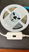
Also is the power source coming in from a USB connector into a cable to this LED strip control box, with its LED + photocell waving detector.
SOME OBSERVATIONs AND TALKING POINTS . . . . . .
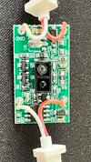
On the top side of the PCB components mounted side.
At the top, a white wire is power ground and the right side RED wire should be +5VDC , if being supplied from a USB connector, but WHAT is that USB connection being made into ? a piece of computer equipment or ? a stand alone wall wart USB power supply ? and are these then just being left continually plugged into the power source, or is there an additional in line power switch also being involved ?
OTHERWISE . . . .why wouldn't just a hand wave ,suffice to turn off the light strip, if the LED strip turns on all of its LED's upon initial powering up. Then the LEDs are being off until a hand wave turns them on and then off, as needed later on.
THE WAY I AM SEEING ITS COMPONENTS RELEVANCE . . . . . .
+5VDC is coming in at the top 2 wires and a A7 series diode in the + line, used to protect from any mis- polarized power supply application.
U3 pads are for a power transistor or regulator , with it apparently not ending up being used.
Down the left side of the board I am seeing Q1 and Q3 A2 type support transistors. Their circuit function relevance unknown at this stage of the mystery.
Travel across the board to find LD1 surface mount visible LED. With two LED's being used, I am now wanting to see the center top LED as being an INFRARED emitter that shoots its beam / pattern upward, to then be hand reflected down upon the INFRARED detector at center bottom, just below it.
Enter the presence of yet the 3rd surface mount transistor, a J3Y, suspicioned as aiding in interfacing between the output of the INFRARED sensor and the input of the 8 pin IC U1 ???
OR it could be the power interface between the U1 I.C. and the LED string. . . . .
BU T T T T T T T T . . . .moi . . .( I ) am real l l l l y wanting to see the bottom RED LED string wire continually getting power and its WHITE companion wire passing up to the collectors of the two A2 transistors and incoming base drive into the pair, will be driving them into full conduction and getting a ground connection at emitters . . .VOILA . . . . THERE IS LIGHT !
Staying on, until base drive from U1, disappears, after a hand wave reflection.
Confirm that the 8 pin I.C. is assigned as being IC1 or ? and is there being any ID marking on it ?.
Find pin 1 of that I.C. by its recess circle close to it or a U-gap molded in the case on one end.
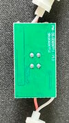
Your PM-DLGD230711-V1.0 "techno gibberish" suggests of a U-processor's involvement and its program version.
For all past times, I don't ever relate the use of a 8 pin DIP . . . being used on case styles for U-processors, nor does the back board shot reveal any epoxy blob COB, being utilized.
HOWEVER the black LED and PHOTOCELL might be mounted atop a U-processor chip ? Which I can not make out.
If you are willing to take a DVM, placed in its DC voltage range and log down the voltage on every pin of the 8 pin unit and then to a hand wave to see what the voltages change to, in the opposite state (on or off) .
Then we might see if the use of a 1-5k resistor connected to +5 or ground and applied to the ascertained chip pin, to assimilate a logic HIGH or LOW might also toggle LED's between on and off.
Then, the use of the delay imparted by a simple dedicated clock reset IC, to toggle the LED lights off after either a power up or power off condition . . . . . according to whichever you would need .
BTW . . . .to pre answer to the question of all of the YO-YO's thinking that U1? is being a 555.
Pin 3 would be LED drive and pin 8 is power, while pin 1 is ground.
SEE BELOW . . . .
 THAAAAAAASSSSSSITT !
73's de Edd . . . . .
A five year olds initial / early on perception of the GOLDEN RULE . . . .
Do one to others as others would do one to you.
.