Maker Pro
Maker Pro

LED Circuit for STEM activity

Human777

May 27, 2016
2
Joined
May 27, 2016
Messages
2
Hi all,

I need to design a circuit as part of a STEM project for kids and could use some help. Basically I need to create a board with a simple diagram of an Oil and Gas process plant, this will be split into 3 ‘zones’. As part of the activity we have 3 ‘alarm/emergency situations’ for each zone- Gas Detection, PW/HC Leak & Fire/Heat. For each zone there should be 3 green LED’s and 3 red LED’s. We want only the Green LEDs to be on to start the activity to simulate that the plant is operating normally. We then want to simulate emergency situations by switching from the green LED’s to the red LED’s, not all at once but one at a time as the activity progresses and depending on which ‘Zone’ the kids are working.


Does anyone have any ideas on how to create this? I would like to keep it as simple and cheap as possible and safe of course!


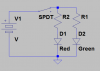
Please see the very crude sketch for info.STEM 2016.jpg
 

Harald Kapp

Moderator
Moderator
Nov 17, 2011
13,754
Joined
Nov 17, 2011
Messages
13,754
Turning an LED on or off is the easy part, see this resource.

How are you goint to activate the changes:
  • Do you have manual switches, potentially hidden from the kids?
  • Do you have sensors? If so, which kind of sensor?
  • Do you need any automatic functions or is everything supervised and controlled by a person?
 

Human777

May 27, 2016
2
Joined
May 27, 2016
Messages
2
Thanks for the response,
  • Do you have manual switches, potentially hidden from the kids? I thought I could either utilise switches or if these are expensive I could manually move the wiring to simulate the different inputs. Everything is to be situated on the back of the board where the kids would not see/have access to.
  • Do you have sensors? If so, which kind of sensor? There are no sensors, the fake alarm LED's are to be set off manually. Part of the follow up is to explain that alarms would be triggered by pressure/temperature sensors etc.
  • Do you need any automatic functions or is everything supervised and controlled by a person? It will be controlled by a person. As there are differing age groups (11 to 16) we have an number of scenarios of varying difficulty which will need some judgement from an adult to help direct the activity.
I was thinking that I could use some form of logic like in my crude sketch. I would need 3 chips with 3 AND gates and 3 with 3 NOT gates, although I am not sure what to use. I was told to look for 7 series chips. Also we decided that breadboards would be the easiest option to set the circuit up on. I was also told that switches for breadboards are expensive and advised to just manually change the inputs to the gates by changing the wiring.
circuit.jpg
Please excuse my poor skill/knowledge level, I am not actually electrical based Engineer!
 

BobK

Jan 5, 2010
7,682
Joined
Jan 5, 2010
Messages
7,682
A simple SPDT swich for each pair will do.

upload_2016-5-27_13-26-59.png

If you want to get really fancy, there are LEDs that will light red with one polarity and green with the opposite polarity. These could be handled with s DPDT switch for each LED.

Bob
 

Attachments

  • upload_2016-5-27_13-26-14.png
    upload_2016-5-27_13-26-14.png
    10.6 KB · Views: 85
Last edited:

AnalogKid

Jun 10, 2015
2,909
Joined
Jun 10, 2015
Messages
2,909
If your circuit is powered by +5 V, you can use 74AC or 74ACT logic chips. These are well-behaved CMOS parts that can source or sink 20 mA per output. You still need current limiting resistors for the LEDs, but you don't need driver transistors as you probably would with 4000 series CMOS gates.

It sounds like for every indication there is one red and one green LED, and it's always one or the other; they never are both on or both off. If this is true, there is a trick that lets you change between two LEDs with only one switch/transistor/logic gate. The left and center schematics below are identical in function. In the center schematic, the combined forward voltages of D4 and D5 in series is approx 2.6 V, while D3 Vf is only around 2.0 V. When the input signal goes high, pin 6 goes low, pulling D3 cathode to ground. Now there is only 2 V across D4+D5, not enough to cause conduction in both diodes and turn on D4. you can swap D3 and D4 for the opposite signal polarity, but D5 always is in the unswitched leg. The right schematic is the same trick applied to a physical switch.

ak
LED-Switch-1-c.gif
 

Attachments

  • LED-Switch-1-c.pdf
    10.7 KB · Views: 51

BobK

Jan 5, 2010
7,682
Joined
Jan 5, 2010
Messages
7,682
Why would you bother with logic gates, when you will need switches anyway, and switches can do the entire job themselves?

Bob
 
Top