Maker Pro
Maker Pro

Input amp with multiple switched jacks

TTL

Oct 24, 2013
187
Joined
Oct 24, 2013
Messages
187
I'm building an input amplifier with two 1/4" jacks (line or mic level inputs). These go on the front panel of a 19" rack enclosure.
In addition to this I'd like to add one more line-level input on the rear of the 19" enclosure.

The tricky part (for me at least) is: how do I connect it so that the rear-panel jack is disabled whenever one of the front-panel sockets have a jack inserted? Below is the schematic, PCB and parts list of the unmodified input amp.

input_amp_1.png input_amp_2.png
 

TTL

Oct 24, 2013
187
Joined
Oct 24, 2013
Messages
187
Oh, I forgot to add that I'm fine with modifying the circuit if needed :)

It's already been redone using Eagle (since having it sent off for PCB production is easier than etching myself the "old fashioned way" (print on to transparencies, UV-lighting, pre-sensitized copper-clad boards, etchant etc.).
 
Last edited:

Harald Kapp

Moderator
Moderator
Nov 17, 2011
13,747
Joined
Nov 17, 2011
Messages
13,747
Use a receptacle with built-in switch. The switch can be used to interrupt (disable) the rear-input when a plug is inserted into the front input.
The rear input itself is wired as the front input with a resistor R4* going to the '+' input of the second opamp, just like R4.
 

TTL

Oct 24, 2013
187
Joined
Oct 24, 2013
Messages
187
Thanks Harald.
Yes, a switched jack for the rear panel sounds about right, but a mono one, right?
I'm not sure if I've got it right, but how does this look? (I might have gotten the jack pins wrong among other things):
input_amp_schematic_rear_input.png

I found the circuit a bit confusing, so I studied the PCB layout and found the jack switch (to the left of R4) to be the GND section of the SK2 (line) jack socket. The German translated article of the same project is clearer on this and other things (though I'm unsure what the "headphone" kind of symbol below RV1 is supposed to mean):
input_amp_schematic_de.png


I am confused about the switching parts of the existing circuit though. It appears that each jack is effectively disabled by having its input switched to GND whenever a jack plug isn't present. I suppose this just makes it completely silent (no input hiss/noise from its pre-amp IC etc.). Then there's the GND-section switch of SK2 (line) socket which I believe disables SK1 (mic) whenever a jack is present in the SK2 (line) socket, but what happens if a jack is present only in SK1 (mic) or two jacks are inserted at the same time (both mic and line inputs)?

Anyway, does my new connection with SK3 (rear panel line-level input) look correct? And will the front-panel line jack have priority over it?
In other words; if I have a jack plug inserted in the rear socket, and a jack is inserted into either the mic or line-level front panel inputs it should disable the rear panel jack.
 

Harald Kapp

Moderator
Moderator
Nov 17, 2011
13,747
Joined
Nov 17, 2011
Messages
13,747
but a mono one, right?
Ideally, but you can use a stereo jack and connect the two 'tip' contacts.
For the switch part, you simply double up the xisting arrangement that turns off the mic input when a line input signal is plugged in:
upload_2016-12-10_16-29-45.png
As to the actual connections to the jack, that's something you either look up in the datasheet or simply measure when you receive the jack(s).
 

Attachments

  • upload_2016-12-10_16-26-17.png
    upload_2016-12-10_16-26-17.png
    101.7 KB · Views: 126

TTL

Oct 24, 2013
187
Joined
Oct 24, 2013
Messages
187
Thanks for correcting the schematic :)
I think I'm misunderstanding the jack symbols in relation to the schematic and how they actually work. There's also a minor difference in the SK1 and SK2 jack symbols, so perhaps two different types should be used? The documentation only says "jack sockets" in the parts list so I assumed the two sockets I illustrated would work.
I looked up several datasheets including Neutrik's Jack circuits PDF document which appears to indicate several different switch configurations. Neutrik_switched_jacks.png

The only types I've had any experience with join/cut a signal whilst also supplying it to the inserted jack's "tip" or "tip" and "sleeve". Should I be looking for a jack socket with some sort of switch which is activated by the insertion/removal of a plug but not connecting to it? The datasheets don't go into this sort of detail

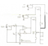
It appears that the SK2 "tip" switch is the switched jack symbol on the right, and the leftmost switch shows the "sleeve" connected/cut to GND. So according to the schematic it appears that I need two SK2 switched mono sockets to make this work.
How (and why) could I use a stereo jack to join this together when there are 4 separate signal sources? Also, with a stereo socket a mono jack plug will be shorting the "sleeve" and "ring" together.

To further complicate things (sorry) :eek: I would like to add, if possible, a female XLR panel connector to the mic input (such as used in the Roland SVC-350 vocoder, below).
Circuitry for converting it into a balanced signal before it enters the mic input (same as the jack connections) would be ideal. Obviously it also needs to be switched (so that an inserted line-jack (rear) will be disconnected or make a mic-input jack plug disconnect. I don't know if there are XLR sockets with built-in switches (to "detect" an inserted XLR plug) -at least I haven't found anything when searching the web yet, but perhaps this could be made by making an opening to the socket and fasten a micro-switch there.
Does this sound doable?
SVC-350 5.jpg

EDIT: found it!! :)
Yes, Neutrik actually has a switched 3-pin XLR female socket: NC3FBV2-SW.
nc3fbv2-sw.jpg
nc3fbv2-sw-rear.jpeg
NC3FBV2-SW -switch illustration.png


EDIT2: this must be my lucky day because I found something equally interesting: a combined jack and XLR socket with switches: Neutrik NCJ-10FI-H.
ncj10fi-s.jpg
neutrik_combo.png
 
Last edited:
Top