Yes, of course.
Perhaps this is assumed by the questioner, though I'd never seen 5 Tc in textbooks - just a rule of thumb for practical chaps. (And I do wonder why one would want to know the 5 Tc discharge time?)
Anyhow, the only thing to do is to calculate the time constant, then explain how you draw your conclusion based on that.
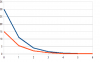
On Laplace's point about how long the capacitor has been charged before you flip the switch, from a few rough calcs I've done, it doesn't seem to make much difference. As you say, after 5 Tc, it's changing very little, 99.5% of the change has happened and the difference due to the starting point has been reduced to 0.5% of the initial difference. Discharging from 15 V instead of 30V doesn't make a difference of 1 Tc after 5 Tc. (attachment) Though it would make a difference to the level at 1 Tc.
The useful point to make for the OP here, is that capacitors are not much use for timing more than one Tc - the time error for any voltage threshold is too great. If you use a capacitor for timing, like in 555 circuits, you need to set your threshold voltage where the capacitor is (dis)charged to no more than about 50%.
And whatever one says in formulae / equations, I don't think you can beat looking at the exponential graph to get a feeling for what's happening. Just imagine trying to read off the voltage when the graphs reach 5 Tc.