Gillesfizzog
- Jan 14, 2014
- 18
- Joined
- Jan 14, 2014
- Messages
- 18
I have been working on an idea for a charge controller for some time now. I feel that i've nearly finalized the idea. If someone could tell me if they think it will work or not, that would be cool.
I've attached the schematic of of this idea to this thread. Ill run you through it step by step.
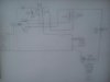
Just to clarify, this design is intended to show how a solar panel can charge a battery during the day while supplying power to a load if needed. Furthermore, The battery will be disconnected when it is fully charged, but the solar panel will still be able to supply the load.
In the circuit:
- There are 3 Push Button Switches, (S1, S2 and S3)
- S1 is normally open
- S2 is normally open
- S3 is normally closed
- There are 3 relays, (R1, R2 and R3)
- There is a small battery on the top left which is part of a separate circuit to affect R1 and R3.
- There is a solar Panel (Far left)
- There is a battery (Slightly right from the center)
- There is a Light on the bottom right to be used as a temporary load, (L)
- There is a receptacle on the bottom right for a potential Load
- The way the relay switches are in the picture are the way they are normally, (Coils are not energized in the picture)
Process:
1. S1 and S2 are pressed at the same time (they close), S1 provides a closed circuit with the light than S2 can energize the coil of R1.(which switches the switch in R1).
2. Now that R1 is switched the electricity is able to switch R2( which closes the circuit through the bigger battery) and switching R3 which closes the separate circuit permanently.
3. Now the Battery is being charged. From the research that i have done, as the absorption stage of the battery progresses, the resistance of the battery rises until the current drawn by the battery becomes very low. All my relays are set to energize at 0.5 amps. When the battery is charged it will draw less than 0.5 amps, which is less amps than the relays need to be energized.
4. You might be wondering what the push button S3 is for,, well, S3 is timed to open the circuit to the load every 10 minutes. the reason i want it to do that is because when the battery is charged and drawing less than 0.5 amps, i want the relays to DE-energize and the circuit to bypass the battery charging. (S3 makes sure that the battery is the only load so to DE-energize the relays.) This protects the battery of over-charging.
- Overnight the battery can be used down to 70% of its charge, ready to be charged the next day.
I've attached the schematic of of this idea to this thread. Ill run you through it step by step.
Just to clarify, this design is intended to show how a solar panel can charge a battery during the day while supplying power to a load if needed. Furthermore, The battery will be disconnected when it is fully charged, but the solar panel will still be able to supply the load.
In the circuit:
- There are 3 Push Button Switches, (S1, S2 and S3)
- S1 is normally open
- S2 is normally open
- S3 is normally closed
- There are 3 relays, (R1, R2 and R3)
- There is a small battery on the top left which is part of a separate circuit to affect R1 and R3.
- There is a solar Panel (Far left)
- There is a battery (Slightly right from the center)
- There is a Light on the bottom right to be used as a temporary load, (L)
- There is a receptacle on the bottom right for a potential Load
- The way the relay switches are in the picture are the way they are normally, (Coils are not energized in the picture)
Process:
1. S1 and S2 are pressed at the same time (they close), S1 provides a closed circuit with the light than S2 can energize the coil of R1.(which switches the switch in R1).
2. Now that R1 is switched the electricity is able to switch R2( which closes the circuit through the bigger battery) and switching R3 which closes the separate circuit permanently.
3. Now the Battery is being charged. From the research that i have done, as the absorption stage of the battery progresses, the resistance of the battery rises until the current drawn by the battery becomes very low. All my relays are set to energize at 0.5 amps. When the battery is charged it will draw less than 0.5 amps, which is less amps than the relays need to be energized.
4. You might be wondering what the push button S3 is for,, well, S3 is timed to open the circuit to the load every 10 minutes. the reason i want it to do that is because when the battery is charged and drawing less than 0.5 amps, i want the relays to DE-energize and the circuit to bypass the battery charging. (S3 makes sure that the battery is the only load so to DE-energize the relays.) This protects the battery of over-charging.
- Overnight the battery can be used down to 70% of its charge, ready to be charged the next day.