Maker Pro
Maker Pro

Help needed decyphering a wiring diagram and resistor purpose

evilstuie

Aug 1, 2023
5
Joined
Aug 1, 2023
Messages
5
Hi All,

First post on the forums, and in need of a bit of help. I've always tinkered with electronics but have never really learned the basics, just what I needed to know when I needed to.

I'm building a "sort-of" replica of KITT from Knight Rider and have created a custom dash from a 19" touch screen, 24" touch screen, 10" Android Tablet and an incar-pc, all of which somehow doesn't include the ability to have a fuel gauge.

Enter Arduino/ESP32 and I'm trying to follow a guide from King6Fab.com for a ESP32 controlled GC9A01 1.28" LCD display to make a pod fuel gauge for my car.
The fuel sender uses a 5v reference in one end and a float that moves a (grading?) resistor from 240ohms at full to ~33ohms at empty, which as I understand it is read as a voltage back at the display end which drops based on how much resistance is added from the float sensor.

As I understand it, the ESP32 boards can only read/handle 0-3.3v so the 5v needs to be brought down to this range to work.
So I either need to bring 5v down to 3.3 on the receiving pin, or alternatively use 3.3v reference and adjust the read voltage on the receiving end, which I need to do anyway.

So here are my 2 questions:

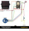
In the attached diagram I am unclear as to what the 100 Ohm resistor's purpose is. Would this be bringing the voltage down, or just adjusting the resistance range (The original design for this was for a 0-190 ohm sensor, but is said to work with any fuel sender range)?

Secondly, in the diagram, the resistor is connected between the 5v reference and the fuel sender, but then the Pin15 which is reading the signal(return signal from the sender after passing through the addon resistor) is connected to the fuel sender side of the resistor which is also supplying the voltage to the fuel sender. That is, there is no 2nd wire coming from the fuel sender, which I would assume is needed: a reference voltage, and a modified varying voltage based on fuel tank level.

Am I not understanding the concept here, or is the diagram wrong?

The only 2 reasons I could see for the single wire, is either the original design accounts for the original car's wiring to continue to supply the original voltage, but then why is the 5v being used?

Or the sender unit uses a ground and measures the resistance that way, but I was of the understanding the ESP & Arduino pins can't measure resistance directly, and it would need a board ground to do this accurately anyway?

Any help for this is greatly appreciated.
 

Attachments

  • ESP32FuelGaugeWiring.jpg
    ESP32FuelGaugeWiring.jpg
    307.8 KB · Views: 17

kellys_eye

Jun 25, 2010
6,514
Joined
Jun 25, 2010
Messages
6,514
The 100 ohm resistor and the resistance of the fuel sender form a simple voltage divider. Using the values given (100 ohms, sensor 240 ohms) and the 5V reference from the ESP module supply, the output voltage from the sender to pin 15 will vary between 3.5V (max) and a lower value (assuming 33 ohms) of 1.24V.

If you can get away with the higher voltage (3.5V) - and you probably can - then leave it as-is. If you want to be 'safer' then increase the 100 ohm resistor to 120 ohms and the maximum voltage becomes 3.3V.
 

evilstuie

Aug 1, 2023
5
Joined
Aug 1, 2023
Messages
5
Hi kellys_eye. Thanks for that. That part makes sense, my only question remaining now is the diagram. The part where both the Pin 15 input source and the end of the resistor prior to the wire going to the sender... is this a graphical mistake?
Am I correct in that the resistor wouldn't do anything if it is just connected as shown there?
The resistor would drop the voltage to around 3.5v as you stated, but the Pin 15 value would then just read 3.5v always, regardless of what the sender is returning?
Also am I correct the 3.3VIN is labelled incorrectly and is actually an output?

I'm assuming the correct diagram would be the 5v line with 100 ohm resistor in line going to the sender unit for reference, and the pin 15 running from other other side of the sender variable resistor to give the fuel level by voltage.
Would that be right?
 

evilstuie

Aug 1, 2023
5
Joined
Aug 1, 2023
Messages
5
Was that meant to be ironic?
Or did you just post a useless semantics point about the terminology of the drawing as demonstration of something some might say, is useless crap?
 

kellys_eye

Jun 25, 2010
6,514
Joined
Jun 25, 2010
Messages
6,514
The part where both the Pin 15 input source and the end of the resistor prior to the wire going to the sender... is this a graphical mistake?
The 3.5V would only be there if the other part of the divider (the level sender) was connected. With either one removed you wouldn't get a reading.

Also am I correct the 3.3VIN is labelled incorrectly and is actually an output?
Can't see the actual text (too small) but that pin DELIVERS a 3.3V supply from the onboard regulator and is capable of driving the LCD module as show so is 'correct' as far as it goes.

I'm assuming the correct diagram would be the 5v line with 100 ohm resistor in line going to the sender unit for reference, and the pin 15 running from other other side of the sender variable resistor to give the fuel level by voltage.
Most fuel senders are simply resistors in and of themselves - they aren't 'potentiometers' as we would usually expect i.e. two sides and a wiper connection (for the output). The 100ohm resistor AND the sender form the divider, the junction of them both becoming the 'wiper' so when the sender resistance varies you get the appropriate divider response at the junction of them both.
Was that meant to be ironic?
What part? If you mean the last part (changing the resistor to 120 ohms?) then no. The analog input of the board states a maximum of 3.3V but a tolerance is allowed (where 3.5V shouldn't pose an issue) BUT it might be that your main supply (5V) is a little higher (it can be) which means the 3.5V could go higher and THAT could be a problem for the analogue input port. Increase the 100 to 120 drops the voltage at the analogue port to keep it in a 'safe area'. You can go to 150 ohms or 180 ohms - it wouldn't make much difference other than you'd have to recalibrate (in software) to counter for the lower span voltage coming back from the sender.
 

kellys_eye

Jun 25, 2010
6,514
Joined
Jun 25, 2010
Messages
6,514
The fuel sender uses a 5v reference in one end and a float that moves a (grading?) resistor from 240ohms at full to ~33ohms at empty, which as I understand it is read as a voltage back at the display end which drops based on how much resistance is added from the float sensor.
If you're using a MODERN sender that derives the fuel level from a potentiometer connected across a 5V supply and takes the reading from the wiper (output) then it's a different matter. The original schematic assumes a 'standard' car sender (two-wire).

The modern sender will output anything from 0-5V which will damage the 3.3V MAXIMUM input of the analogue port. In this case you'd apply 5V directly to one side of the sender (forget the 100 ohm resistor), the other side of the sender to ground and take the output from the wiper to another pair of resistors calculated to reduce the signal so it can't exceed 5V.

This would be (for the sake of simplicity) a 120 ohm resistor and 240 ohm resistor connected (in series) across the 'wiper' (sender signal) and to ground where the junction of the 120/240 resistors would deliver the 'divided' (not exceeding 3.3V) voltage to the analogue input port.

In practise you'd need resistors of higher values (say 12k ohms and 24kohms) so they didn't affect the resistance of the modern sender. You could also use 120k and 240k. For the sake of simplicity (using the E12 range of resistors) use a 12k and a 27k across the sender output.
 

Harald Kapp

Moderator
Moderator
Nov 17, 2011
13,747
Joined
Nov 17, 2011
Messages
13,747
Was that meant to be ironic?
I don't think so.
There's a big difference between a pictorial style diagram and a schematic style diagram (see here). While both represent the circuit:
  • a pictorial style diagram shows how physical components are wired. This may seem intuitive to the layman, but may actually result in a cryptic image where the function of the circuit is hard to decipher.
    For example: if the image shows a blue wire connected to pin 1 of a pcb (not referring to your actal example!), this is what one may actually see with the wired components in front, but it does tell you absolutely nothing about the signal on the blue wire or the function of pin 1.
  • a schematic style diagram on the other hand may seem cryptic to the layman, but offers a clear insight into the operations of a circuit to the expert.
    For this kind of diagram it is irrelevant, for example, which color a wire has or where on the pcb the pins are located. What counts is the function of both and how they are related to each other.
 

kellys_eye

Jun 25, 2010
6,514
Joined
Jun 25, 2010
Messages
6,514
Was that meant to be ironic?
Oops, didn't see Bluejets post (the one you made the 'ironic' reference to).

Yes it was 'ironic' as the wiring diagram isn't what we expect as standard - it's derived that way for 'simple people' (none intended!) who just need to follow a point-to-point wiring arrangement rather than look at it from its true technical aspect - as we prefer.
 

sgodblacktechy

Jul 27, 2023
11
Joined
Jul 27, 2023
Messages
11
The 100 Ohm resistor probably adjusts the resistance range. The single wire connection might be for a ground reference. You can use a voltage divider or a 3.3v reference to make it work.
 

evilstuie

Aug 1, 2023
5
Joined
Aug 1, 2023
Messages
5
I just wrote a small code to check the values of a spare fuel sender unit I had, and the voltage doesn't seem to drop when I move the float.
The ohms are mapped to the A0 analog input from 0-1023, 30-240, but will always read at 240 unless I disconnect it. I tired using both 3.3v and 5v reference. I confirmed it is working by testing ground resistance and it works, increase as the float moves upwards.

It seems that the Arduino unit is just supplying more/less current to compensate for the increase/decrease in resistance. Does this sound right?

The easy answer would be to just use a ground reference, but Arduino can't measure resistance, only voltage I think.

I've attached an image of the sender unit style for reference.

I'm going to try using an external source for the 5v supply and try and just read the voltage itself on a multimeter to see if the sender is actually dropping the voltage or remaining constant.
I was curious how the Analog pin on the Arduino would know what voltage is being used though, as it didn't change the scale or value when I switched between 5v & 3.3v though.

Apologies if I'm getting everything mixed up. I'm just realising there's a larger base knowledge needed for this task than I previously thought so trying to learn some of the basics.
 

Attachments

  • sender.jpg
    sender.jpg
    164 KB · Views: 0

kellys_eye

Jun 25, 2010
6,514
Joined
Jun 25, 2010
Messages
6,514
You MUST use a second resistor in series with the sender in order to create a potential divider - the junction of the two resistors being where you will measure the 'change' as one of the resistor values alters (the float moving).

Without this second resistor all you are doing is varying the current through the sender resistance
It seems that the Arduino unit is just supplying more/less current to compensate for the increase/decrease in resistance. Does this sound right?
and run the risk (not from the Arduino fortunately as it's incapable of delivering a high enough current) of burning it out.

In a vehicle, this 'second resistor' is the gauge itself but the analogue input port of an Arduino doesn't have any resistance to speak of.
 

evilstuie

Aug 1, 2023
5
Joined
Aug 1, 2023
Messages
5
Perfect, thanks for that explanation. I've only ever really wired things where they needed a power source, a ground or an input of one or the other. Until today I assumed a completed circuit was a single closed loop, and measuring before and after the resistor confused me but I get it now. I was also wondering how I could get voltage reading without a ground but this also explained it.

I now have the Arduino unit ready values and plotted against a 8x8 LED matrix with the fuel values assigned into 64 fractions to give me a light for each portion of fuel to turn off as the tank drops, so I just need to transplant it into the dash or pillar gauges and I'm all sorted.

Thanks for the help
 
Top