Maker Pro
Maker Pro

help fixing fluorescent lamp circuit

pharaon

Oct 28, 2014
444
Joined
Oct 28, 2014
Messages
444
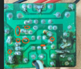
This is an electronic neon bulb circuit. Two transistors No. 13003 were changed. Two quarter-watt resistors, 15 ohms. The rest of the resistors and diodes are good. When connected, the bulb lit for a few seconds, then a spark came from the two transistors 13003, and I found that they were shorted. Also, the two 15 ohm resistors burned out. What is the cause of this malfunction? Note that two chemical capacitors were checked, they were good, all diodes were checked, and all resistors were checked.
i dismantled 3 green ceramic capacitors and measured them with an multimeter, and they gave the correct results
2A333j = 33nF
222j = 2.2 nF
682j = 6.9 nF
i'm not sure what is the cause of this failure, this is the second time to change 13003 transistors.

426279283-335489786203299-71464191732262141-n.jpg

435675000-335489999536611-5579993616475901757-n.jpg

436014813-335489949536616-1449358390806637585-n.jpg

436139162-335489819536629-5957124858871835603-n.jpg

436407179-335489816203296-6124032482347240498-n.jpg
 

Delta Prime

Jul 29, 2020
1,994
Joined
Jul 29, 2020
Messages
1,994
Can you take a photograph of the neon bulb? Please...
Your lamp that uses a neon bulb, does it have a manufacturer's name?
All these solder blobs must be cleaned off with 99% alcohol.
photo_1712508771715.png

i dismantled 3 green ceramic capacitors and measured them with an multimeter, and they gave the correct results
2A333j = 33nF
222j = 2.2 nF
682j = 6.9 nF
i'm not sure what is the cause of this failure.
Those are not green ceramic Capacitors, although they exist. What is on your board is a film capacitor (non- polarized) electrostatic Polyethylene Terephthalate (PET) film capacitor.

Name,type of the multimeter you are using. Did you check the components "in-circuit"? or did you physically take him off of the PCB for testing?
 

73's de Edd

Aug 21, 2015
3,629
Joined
Aug 21, 2015
Messages
3,629
ARAB----------> ENGLISH . . . .update . . . . . . make that Compact Fluorescent Lamp instead of "neon" . . . . . .as if a person couldn't recognize that circuitry already ?
ASIDE . . . .
Check the filaments of the lamp, if both / (Siamese twins) are not reading 10-ish-20-ish ohms I would give it up . . . with so many parts blown already . . . . . it just being a fun / educational fix again, anyway.
These will be dinosaurs after existing stockpiles are depleted.
 
Last edited:

Bluejets

Oct 5, 2014
6,953
Joined
Oct 5, 2014
Messages
6,953
Perhaps your filter circuit is not working properly. (bad or leaky caps)
 

73's de Edd

Aug 21, 2015
3,629
Joined
Aug 21, 2015
Messages
3,629
Sir Pharaon . . . .

I wish that the foil side of the board would have been cleaned of flux residue and dark coloring BEFORE photo was taken. . . . I am now having high degrees of uncertainty . . . . with viewing problems.
Can you redo this schematic that I supplied to agree with your circuit boards components or tell me, so that I can re do it.
Initially, we can see that the top left corners inductor was NOT being used on your board, and confirm the use of an incoming fuse resistor.
Your board DOES use the main back EMF inductor on that smaller board as well as a capacitance reactive voltage dropper, on that small board, but the cap may be of a different value.
On schematic work . . . .
I have already gone over to the two ORANGE main filter capacitors and drawn them in correctly, as being in series. To give a WHOPPING 500V safety margin . . . max . . . .rating, to your potentially expected ~320-340VDC supply
I need to see which is the DIAC location, as all of the other like cased diodes are being of the 1N4007 series.
That CFL lamp was not what I was expecting, I see the wattage but no reference to length. . . .I was expecting a bent or corkscrew lamp.
An 18W lamp should initially FIRE to ionize, and then settle down and stabilize with an ~50-60V across it at ~300'ish ma current consumption.

HERE IS THE RELATED IMAGING . . . . ( left CLICKEE-MAKEE- IT -----------MO !!! BIGGGGGEEEE )

PHAROAN-CFL-LAMP-CIRCUIT.png


73's de Edd
 
Last edited:

bertus

Moderator
Nov 8, 2019
3,337
Joined
Nov 8, 2019
Messages
3,337
Hello,

One note, the circuit will only work correct when both filaments of the CFL are still ok.
Have a lookat this page for some more schematics:

Bertus
 

pharaon

Oct 28, 2014
444
Joined
Oct 28, 2014
Messages
444
i think there's some misunderstand

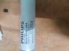
this is the type of lamp i'm using
61-DVd-FF9f-L.jpg


Can you redo this schematic that I supplied to agree with your circuit boards components or tell me, so that I can re do it.
Initially
this is new picture for the board after it been cleaned .
notice:
I removed two transistors to replace them.
I also removed to ceramic capacitors in order to test them as well
I'll re connect all after figuring out what's the issue exactly
the red wires are the AC in
the white and black wires are going to the other side of the lamp

IMG-20240409-181621.jpg

IMG-20240409-181721.jpg

IMG-20240409-181741.jpg

IMG-20240409-183233.jpg

IMG-20240409-183208.jpg
 

Martaine2005

May 12, 2015
4,955
Joined
May 12, 2015
Messages
4,955
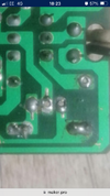
Did you take the photos with a potato?:)
I can see some terrible solder joints. Hopefully the forum can accept my image.
 

Attachments

  • IMG_4493.png
    IMG_4493.png
    1.1 MB · Views: 6

bertus

Moderator
Nov 8, 2019
3,337
Joined
Nov 8, 2019
Messages
3,337
hello,
i think there's some misunderstand

this is the type of lamp i'm using
the principe for an electronic ballast is the same for your tube and a CFL.

bertus
 

Bluejets

Oct 5, 2014
6,953
Joined
Oct 5, 2014
Messages
6,953
Some one has been fiddling and has everything a-up.

2nd last photo in # 10 definitely not right.
Bye bye to at least one tube heater.
 
Top