Maker Pro
Maker Pro

Fm transmitter help

Simon duvall

Sep 28, 2015
3
Joined
Sep 28, 2015
Messages
3
Hi guys,

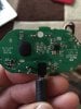
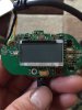
I'm looking for some help with my current project, I need to extend the range of my Belkin tune cast II fm transmitter as at present its range struggles to exceed 5 feet. Having googled for hours I can only find tutorials for the version 1 which had a surface mounted attentuator which could be bypassed to allow a stronger fm signal. However with my version (I believe it's the 2nd release) the pcb has a different layout. I have been informed that if I can locate the fm tx chip that I can add a new attenna directly to the output leg. However I cannot establish which chip I need to be soldering to and would appreciate any help you guys could give me.
 

Attachments

  • image.jpg
    image.jpg
    254.2 KB · Views: 166
  • image.jpg
    image.jpg
    238.8 KB · Views: 196

Arouse1973

Adam
Dec 18, 2013
5,178
Joined
Dec 18, 2013
Messages
5,178
Hi Simon
Modifying the range of an FM transmitter from what is was designed to do is not allowed in the UK. But looking at information for the device it says 10 to 30 feet. You only have 5 feet so your antenna might be broken, I have circled what I believe to be the antenna connection. Feel free to have a look around this area to try and fix your unit. Trace the track back from there and see if you can see any broken components. The little square IC on the other side of the PCB from what's shown here might be the RF device. See if you can read the part number and have a Google or report back here.
Thanks
Adam

belk.PNG
 

Simon duvall

Sep 28, 2015
3
Joined
Sep 28, 2015
Messages
3
Hi Simon
Modifying the range of an FM transmitter from what is was designed to do is not allowed in the UK. But looking at information for the device it says 10 to 30 feet. You only have 5 feet so your antenna might be broken, I have circled what I believe to be the antenna connection. Feel free to have a look around this area to try and fix your unit. Trace the track back from there and see if you can see any broken components. The little square IC on the other side of the PCB from what's shown here might be the RF device. See if you can read the part number and have a Google or report back here.
Thanks
Adam

View attachment 22242


Many thanks for your help and advice, I acknowledge your comment regarding the alteration of the fm range, I am however using his piece of kit for a few hours in a field in the middle of the countryside as part of a larger experiment, so hopefully I won't cause anyone any aggravation!

I should have mentioned that I have removed the antenna wire already, as it was suggested that replacing with a 1/4 wave antenna would provide the extra range, unfortunately this modification didn't have the desired results, so my only other option is to solder directly to the output pin of the transmitter chip before the signal strength is restricted.

the part number on the chip is as follows :

8007511405 suu08
 
Last edited:

Arouse1973

Adam
Dec 18, 2013
5,178
Joined
Dec 18, 2013
Messages
5,178
This maybe the output inductor L1, trace back from the antenna and see if it connects here. The other thing is the IC may have settable gain using a resistor divider or something along those lines and no matter how you connect your whip you will be limited by the output power of the device. I can't find any info on those numbers you gave, it might be an ASIC chip they had made or they have had a chip numbered for them.
Adam

belk2.PNG
 

73's de Edd

Aug 21, 2015
3,629
Joined
Aug 21, 2015
Messages
3,629
.


Sir Simon. . . . . .( sez ? )

Looks like earlier versions of those units had FAR MORE discrete components being used in their boards design.
On those, the FM RF circuitry was showing its enamelled wire/air wound coil, plus the FM stereo to RF IC was using a micro flat pack BHF1415F.

As per your newer Nov of 2011 board design of the Model II, it seems to be using the I.C.markups I have shown below on your now marked up photo.

On the mini male audio plug, in looking at its cable break out to the PCB interconnect points, a given
is for those yellow and white wires to be the R and L channel audio inputs.
Now, being hidden, within the "black twisted mass," I am expecting a common shared ground wire for those audio signals and . . . . being heavee on the AND . . . . yet another wire, which transverses the whole length of the "doggles" internal wiring, but is cut off and being unterminated at its very end, near the AF plug.

That is being the units intentionally SHORT RANGE radiating antenna wire.

It initially was connected to the very end terminal marked ANT on the pcb.

That pcb ant terminal PRESENTLY seems to have a short ( 0.445765 cm) length of 10 strand hook up wire, that has but a SOLE strand of its #30 wire, that is extending out a full (1.72843 cm) to now be your very SHORT RF radiating element/antenna/aerial.

An infinitely closer inspection, further suggests of its "tack soldering" operation, possibly being performed by a 89 year old male with SEVERE palsy and of his using a 360 watt WELLER soldering gun. (Possibly, also, the use of acid core solder.)
Heh . . .heh . .heh . . .a jestingly poke to your ribs and a wink- wink.;)

Looking at the photos supplied, the main brains of the unit and digital processing for the LCD display counter and feed line of address lines to the synthesizer seems to be under the [YELLOW] marked epoxy blob that covers up/seals its Circuit on Board I.C.

The other more familiar looking [ RED BLOCK] IC will be the FM RF synthesizing Stereo modulator and RF output function for the unit.

It is yet an unknown as to how much "punch" this newly revised RF design has.

Lets start by either using some fine insulated wire like #26-30 ga Kynar wire wrap wire, OR if you dont have such.
Use about a 39 inch length of that same previously mentioned insulated and stranded wire BUT strip off one end of 1/4 of an inch of its insulation.
You then separate the strands such that all of the wires can be clipped off excepting only one, and that will be the one to be pre-tinned with solder and then used to tack solder into the PCB.

( If this mod finds it being adequate on signal strength, a healthy blob of hot glue / or /epoxy later supports the wire for further insulation and mechanical rigidity.)

You now take that pre tinned strand and solder tack it to my RED arrow referenced connection to the RIGHT side of L1 inductor.

Lay out your new "antenna wire in a flat plane and fire up the system and use a FM portable radio to now check out the systems max transmit range.

How goes it now ?

Aside tasks, is to feed info back to me . . . . since I'm being blind-deaf and DUMB at this end.

Also confirm for us:

That tinned test point exposure TP 16 (?) over to the right bottom corner is showing ~ zero ohms in a continuity check between it and the LEFT side of that L1 inductor .( The BLACK ARROW)
(That connection presence would preclude the need for test probe "piercing" of the hard green resist cover of that whole ground plane area.)

Pull out a BRIGHT light and MAGNIFIER to pass on all of the numbers being on that RED chip, and ALSO the 8 pin dip IC ? of the RIGHT top corner of your OTHER photo . . . . its being located at right top corner from the LCD display.

Thassssssssssit . . . .now . . . go ye forth and . . . do it . . . . to it !


(Pee Ess . . . . .if the units altered performance is still being under 2km (+/- 1.999995 km) range . . .wink/wink ;) . . . . there is a further "altercation" which involves the touchy heating and micro tweezer lifting (shuddddder) of L1 choke, to be out of circuit . )


73's de Edd


Photographic Tech Referencing:
(Click on photo to MAG)


ZEOU4pA.jpg


Poked up EARLIER, therefore it may not be reflective of others later comments .


73's de Edd


.
 
Top