Maker Pro
Maker Pro

Few Questions about Sound on Light

davenn

Moderator
Sep 5, 2009
14,267
Joined
Sep 5, 2009
Messages
14,267
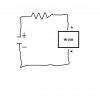
Well the IC mixes the incoming signal (diode converts signal from AM, which strips the signal for voice or in the case of FM - sound) with the tuner signal coming from the tuner and then combines the 2 signals to go out of the 'output' and into another IC (not sure if the first one is 555 Timer or this one) which mixes the signal with the chosen level of sound from the amplifier and then comes out of that output.

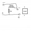
this part i am having difficulty in. You said to convert the signal into light (hence the intensity would be provided by the previous circuits before it reaches this stage), i would need a photo-transistor thing? What ever is the component that converts sound signals into Light is what goes after the 555 Timer. Then that goes into the input of the Transmitter (which has the coils and caps tuned to the freq of Infra-red) and out through the LED.

I believe this is possible (the last part about the Infra- Red freq) as we use this Freq for remote controls and other uses.

Anyway, that is what the IC is for.

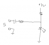
think if the AM/FM signal received by the receiver is amplified by a transistor or 2 then it should provide enough to send back through to the input of the 1st circuit with the battery source. Then the only problem would be to limit the amount coming into the circuit with a voltage regulator. But i'm wondering if the diode should come before the voltage regulator? i think it would explode, won't it? Still not sure. Further testing is required, which i will do.

Electro

you need to stop making these totally off base statements ... they truely make no sense at all :(
please Please PLEASE go read some books on radio transmission and reception
learn about how those things work, how modulation is added to them

Also read up on how to modulate a LED ( be it laser, visible, or IR types) with an audio signal and how you would receive that LED light and recover the audio

When you have done all that reading, then you will be able to come back and ask some good questions on the bits you didnt understand :)

if you dont do those things BEFORE coming back and asking some good questions, I will lock this thread OK ?

Dave
 

Electro132

Feb 12, 2013
261
Joined
Feb 12, 2013
Messages
261
Electro
When you have done all that reading, then you will be able to come back and ask some good questions on the bits you didnt understand :)

if you dont do those things BEFORE coming back and asking some good questions, I will lock this thread OK ?

Dave

ok fine. No hard feelings felt here. I'll build it and put it on Utube.....
 

Electro132

Feb 12, 2013
261
Joined
Feb 12, 2013
Messages
261
Thanks for the deletion. Ok so i went and had a look. So far i understand that i need an IR LED which has a resistor to prevent it from burning out. I also learnt that i need to know the supply voltage (i'm planning on 3v), LED forward-voltage drop (usually 1.3V) and the desired current through the LED (which at this point i'm thinking it's 50mA but want to try its full extent at 150mA).

Now i must find the resistor:

To find the resistor voltage drop, I subtracted the voltage drop of the IR LED from the total supply voltage, which is 7.7 v. Now i know that the current must be expressed in Amperes so i divide the mA by 1000 and i get 0.05 A for 50mA (for 150 mA is 0.15 A)

I found the resistance by dividing the resistor voltage drop (7.7) by the current in A (0.05) which gave me 154 ohms resistance. Since i found no such thing i'll go with the closest one: either a 150 or 220 ohm resistor.

So its the resistor connected to the IR LED which has K connected to the negative side.

Ok so how does a wave form generator with Amplifier get connected to it if the amp and freq changes the output? wouldn't the current be too much for the resistor and explode?

And also, i know that Fm radio has waves in it so if i connect that with an Amplifier and the IR LED would it give me the same outcome? Just thoughts.
 
Last edited by a moderator:

(*steve*)

¡sǝpodᴉʇuɐ ǝɥʇ ɹɐǝɥd
Moderator
Jan 21, 2010
25,510
Joined
Jan 21, 2010
Messages
25,510
There's some confusion in my mind as to what your actual supply voltage is (is it 3V or 7.7V?

Either way, you have the general maths right, R = (V-Vf)/I and you have the units correct. You also have the polarity correct.

What you have now is an IR LED turned fully ON. That's going to make IR light, but not transmit anything.

What you need to do is to vary the intensity of the light using your signal (essentially amplitude modulation).

Ok so how does a wave form generator with Amplifier get connected to it if the amp and freq changes the output?

There are a number of ways to do this, but all essentially come down to using the signal to change the current flowing through the LED.

One simple method is to take your LED and resistor, then connect a resistor and a capacitor (in series) from the output of an amplifier to the anode of the LED and connect the other output to the cathode (be careful that the two ground connections are compatible).

The resistor should be chosen so that the maximum LED current through it is limited to the constant LED current. If the amplifier has a 12V rail, do your calculations based on 6 volts. The capacitor should be about 1uF (non-polarised).

This arrangement will cause the amplifier to add and subtract current from the LED.

wouldn't the current be too much for the resistor and explode?

Yes, the maximum current will be about double what you have set up originally, but the minimum will be close to zero. Fortunately these kinda cancel out, so the LED will not complain (it's average power that kills them, not peak power -- within reasonable limits).

So nothing will explode. The currents are small and the average power is likewise small.

And as I've said, the modulation is AMPLITUDE modulation -- can you see that?

The frequency of the light emitted is determined by the physics of the materials the LED is composed of. You are not generating this (i.e. there is no oscillator) and so FM is effectively impossible.

And also, i know that Fm radio has waves in it so if i connect that with an Amplifier and the IR LED would it give me the same outcome? Just thoughts.

I'll pretend I didn't read that. You're making assumptions (wrong, or meaningless) beyond your present comprehension and producing gibberish.

Try not to do that.

Do you think you can draw a circuit diagram from my explanation? Or would you like me to help you with that?

If you can't, do you think you can draw a diagram showing just the LED and the resistor connected to a voltage source?
 

(*steve*)

¡sǝpodᴉʇuɐ ǝɥʇ ɹɐǝɥd
Moderator
Jan 21, 2010
25,510
Joined
Jan 21, 2010
Messages
25,510
Oh, one more thing -- make sure you look at the continuous current that the LED can handle. It may be as low as 20 mA or 30 mA.

Don't worry about this at the moment, there are ways to get around that (but don't exceed that at the moment).
 

Electro132

Feb 12, 2013
261
Joined
Feb 12, 2013
Messages
261
There's some confusion in my mind as to what your actual supply voltage is (is it 3V or 7.7V?

It is 3V but if it gets too hard for me then i'll switch it to 5v or 9v.

Either way, you have the general maths right, R = (V-Vf)/I and you have the units correct. You also have the polarity correct.

Thank you. I am really keen on doing this project ever since i found out about Light being used as a carrier.

What you have now is an IR LED turned fully ON. That's going to make IR light, but not transmit anything.

What you need to do is to vary the intensity of the light using your signal (essentially amplitude modulation).

You mean i can change how much i can put out on an LED using an AM signal?

There are a number of ways to do this, but all essentially come down to using the signal to change the current flowing through the LED.

One simple method is to take your LED and resistor, then connect a resistor and a capacitor (in series) from the output of an amplifier to the anode of the LED and connect the other output to the cathode (be careful that the two ground connections are compatible).

The resistor should be chosen so that the maximum LED current through it is limited to the constant LED current. If the amplifier has a 12V rail, do your calculations based on 6 volts. The capacitor should be about 1uF (non-polarised).

This arrangement will cause the amplifier to add and subtract current from the LED.

Yes, the maximum current will be about double what you have set up originally, but the minimum will be close to zero. Fortunately these kinda cancel out, so the LED will not complain (it's average power that kills them, not peak power -- within reasonable limits).

So nothing will explode. The currents are small and the average power is likewise small.

And as I've said, the modulation is AMPLITUDE modulation -- can you see that?

The frequency of the light emitted is determined by the physics of the materials the LED is composed of. You are not generating this (i.e. there is no oscillator) and so FM is effectively impossible.

I understand. What if an IC like a 4093 model quad Schmidtt NAND gate is used? I read that its switching action, high or low, is more controlled and accurate than a standard gate. I also read that it produces a sharp defined transition from high to low (or vice versa) when the input is gradually changing. Would it make an ideal component for the changing current?

Do you think you can draw a circuit diagram from my explanation? Or would you like me to help you with that?

If you can't, do you think you can draw a diagram showing just the LED and the resistor connected to a voltage source?

I've attached the IR LED just in case.
 

Attachments

  • Simple IR LED.jpg
    Simple IR LED.jpg
    11.4 KB · Views: 93

(*steve*)

¡sǝpodᴉʇuɐ ǝɥʇ ɹɐǝɥd
Moderator
Jan 21, 2010
25,510
Joined
Jan 21, 2010
Messages
25,510
You mean i can change how much i can put out on an LED using an AM signal?

No, just a signal. That will amplitude modulate the light output of the LED.

Here's a partial schematic:

attachment.php


The 3V is shown. The resistor between the 3V and the LEDis calculated for (say) 20mA.

the capacitor and resistor connected between the signal input and the LED add allow the signal to and subtract from the LED current.

The signal has to be a low impedance source (e.g. an amplifier) and the resistor needs to be carefully chosen.

There are practical improvements that should be made, but this indicates the concept.
 

Attachments

  • modulate.png
    modulate.png
    4 KB · Views: 166
Last edited:

Electro132

Feb 12, 2013
261
Joined
Feb 12, 2013
Messages
261
The signal has to be a low impedance source (e.g. an amplifier) and the resistor needs to be carefully chosen.

There are practical improvements that should be made, but this indicates the concept.


Hey I found out what you meant with the cap and res in series for the output of the amp connected to the IR LED.

I've attached it.
 

Attachments

  • Amp & IR.jpg
    Amp & IR.jpg
    13.6 KB · Views: 97

(*steve*)

¡sǝpodᴉʇuɐ ǝɥʇ ɹɐǝɥd
Moderator
Jan 21, 2010
25,510
Joined
Jan 21, 2010
Messages
25,510
No, look at what I drew for you.
 

Electro132

Feb 12, 2013
261
Joined
Feb 12, 2013
Messages
261
No, look at what I drew for you.

Hey i did some calculations and labelled the components. Just want to know if the negatives are the arrows leading to nowhere? Also i took a guess on which resistor it was that would suit the 94 ohm (2x 47 ohm in series) resistor as you can see in the picture.
 

Attachments

  • IR.jpg
    IR.jpg
    40.4 KB · Views: 91

(*steve*)

¡sǝpodᴉʇuɐ ǝɥʇ ɹɐǝɥd
Moderator
Jan 21, 2010
25,510
Joined
Jan 21, 2010
Messages
25,510
You show 2 47 ohm resistors in parallel giving 23.5 ohms, not 2 in series for 94 ohms.

Your calculations are a little off. (and your methodology is questionable)

Input voltage 3V
LED Vf = 1.3V
LED current = 0.05A

LED resistor = (3 - 1.3) / 0.05 = 34 ohms

I would use a 33 ohm resistor (It looks like you did your calculations for 6V)

For the input, I would recommend a 1uF capacitor and I would have started with around 220 ohms, but I didn't mention that anywhere.

You would also be wise to place another diode, reversed, across the LED. This will save your LED from reverse voltage should you turn the volume up too high.
 

sirch

Dec 6, 2012
109
Joined
Dec 6, 2012
Messages
109
Steve - I think you deserve a medal for persisting with this guy for 4 pages!
 

Electro132

Feb 12, 2013
261
Joined
Feb 12, 2013
Messages
261
You show 2 47 ohm resistors in parallel giving 23.5 ohms, not 2 in series for 94 ohms.

Your calculations are a little off. (and your methodology is questionable)

Input voltage 3V
LED Vf = 1.3V
LED current = 0.05A

LED resistor = (3 - 1.3) / 0.05 = 34 ohms

I would use a 33 ohm resistor (It looks like you did your calculations for 6V)

For the input, I would recommend a 1uF capacitor and I would have started with around 220 ohms, but I didn't mention that anywhere.

You would also be wise to place another diode, reversed, across the LED. This will save your LED from reverse voltage should you turn the volume up too high.


Sorry, i changed the resistors to series now. I forgot that series was one after the other. i've added this diagram which used a 555 timer which might make it easier to maintain the current through to the LED just to share.

Would like to know what the difference is between using a 555 timer and one that doesn't?
 

Attachments

  • 555 with IR.jpg
    555 with IR.jpg
    22.3 KB · Views: 113
  • IR2.jpg
    IR2.jpg
    40.1 KB · Views: 134
Last edited:

(*steve*)

¡sǝpodᴉʇuɐ ǝɥʇ ɹɐǝɥd
Moderator
Jan 21, 2010
25,510
Joined
Jan 21, 2010
Messages
25,510
Electro132, you need to go back and re-read ALL of my message.

Just reading the first couple of words is not sufficient.

A single 47 ohm resistor would be closer to what you want.
 

Electro132

Feb 12, 2013
261
Joined
Feb 12, 2013
Messages
261
Electro132, you need to go back and re-read ALL of my message.

Just reading the first couple of words is not sufficient.

A single 47 ohm resistor would be closer to what you want.


My apologies again, i uploaded the wrong pic. Thanks for the correction. Here' it is with 6v and 3v. Just with the protection diode, what is the difference between a normal diode and a zener diode? I read both. According to what i read, the Zener is special because it has a voltage threshold which allows it to conduct the other way when it reaches that threshold. Both normal diodes and zener diodes have current flow in one direction. But i was just wondering what happens when the zener diode's threshold gets reached? Wouldn't it start to bring back the electrical charge to the source, meaning it will fill up the source battery and explode?
 

Attachments

  • IR.jpg
    IR.jpg
    40.3 KB · Views: 120
  • IR2.jpg
    IR2.jpg
    38.8 KB · Views: 115
  • 555 with IR.jpg
    555 with IR.jpg
    22.3 KB · Views: 117

(*steve*)

¡sǝpodᴉʇuɐ ǝɥʇ ɹɐǝɥd
Moderator
Jan 21, 2010
25,510
Joined
Jan 21, 2010
Messages
25,510
In the forward direction normal diodes and zener diodes are pretty similar.

In the reverse direction normal diodes will break down at a (an unknown) voltage higher than the breakdown voltage. Zener diodes break down at a known voltage.

Normal diodes are optimised for forward conduction, zener, for reverse breakdown effects.
 

Electro132

Feb 12, 2013
261
Joined
Feb 12, 2013
Messages
261
In the forward direction normal diodes and zener diodes are pretty similar.

In the reverse direction normal diodes will break down at a (an unknown) voltage higher than the breakdown voltage. Zener diodes break down at a known voltage.

Normal diodes are optimised for forward conduction, zener, for reverse breakdown effects.


ok cool. So the current moves in one direction for the zener and if that zener gets too much voltage input then it breaks down. Does it start back up or is it gone for good after the breakdown?
 

Electro132

Feb 12, 2013
261
Joined
Feb 12, 2013
Messages
261
Breakdown is the normal mode of operation of a zener diode.

Ok cool. So if i place the zener diode the wrong way will it explode?

Also, in turns of an amp, if i use a trimpot and turned it fully in one direction then left it like that, would the current coming into that circuit be amplified alot? And if so, wouldn't i need to use a different resistor to make sure that my desired level of current (which had increased) doesn't blow up any other components it comes across at that level?

one more question, if the LED at the end has a circuit which only allows up to 50 mA to go through it, doesn't that mean that my increased current will make it explode?
 

Electro132

Feb 12, 2013
261
Joined
Feb 12, 2013
Messages
261
In the forward direction normal diodes and zener diodes are pretty similar.

In the reverse direction normal diodes will break down at a (an unknown) voltage higher than the breakdown voltage. Zener diodes break down at a known voltage.

Normal diodes are optimised for forward conduction, zener, for reverse breakdown effects.


Thanks Steve. I would also like to build an amplifier for this. Is it possible that the current can be increased so then the amplifier can increase it even more? I'm just worried that the LED might explode.
 
Top