I build the circuit in the diagram that act as a time delay when the opamp which act as a comparator, when the condition is match, the opamp goes high which charge the capacitor instantly, when it goes low, the capacitor discharge through the resistor slowly, the signal is fed to another OpAmp, when I test the cirrcuit in the breadboard, I uses a aluminium electrolytic capacitor of 10uF, the time that it reaches the trigger point for next stage is about 10sec, but when I build the circuit on a PCB, I uses a ceramic multi layer capacitor with the same 10uF, but the time delay shorten to about 2 second, I wonder why this could happened, all the resistor value are the same on the breadboard and the PCB except that the bread board are using through hole resistor and capacitor and the PCB version are using surface mount capacitor,
BTW the capacitor on the bread board are polarized and the PCB version are non polarized
Will the surface mount version have a much lower actual capacitance value than the polarized version?
BTW the capacitor on the bread board are polarized and the PCB version are non polarized
Will the surface mount version have a much lower actual capacitance value than the polarized version?
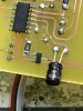
Attachments

Last edited by a moderator: