Maker Pro
Maker Pro

Dual pump control circuit help

bricklayer

Jun 11, 2016
10
Joined
Jun 11, 2016
Messages
10
image.jpg
a>
i had a friend design this circuit for me for my reverse osmosis unit I'm building for my reverse osmosis unit. It's designed to shut both pumps off on low pressure and shut pumps off on high pressure. I'm just starting to put it together and am a little confused on the pressure switch setup. The low pressure switch is in the nc position untill it receives a minimum pressure of 15 psi then it opens. The high pressure switch is in the nc position untill high pressure is reached and its opens. I have attached the explanation of the circuit from the individual that has designed it. Any input is appreciated. Sorry for some reason it's not letting me post images. I will keep trying


OK, here’s what I came up with.

This system uses two relays, two contactors and the pressure switches to monitor the system for high or low pressure conditions.
It should be noted that this circuit was designed specifically for the Dwyer A1PS-44 High pressure cut-off switch. Other switches may be used, but they must operate in the exact same fashion.

As a side note, I’d wire your pumps for 220V if possible. They’ll start easier, run better and a little cooler if you do.

Circuit description:
The main power switch provides power for the entire circuit.
Pressing the LP Start switch will energize relay K2. Once energized, K2 will self-latch, arm the low pressure switch and provide power to the LP pump contactor which turns on the LP pump.
If using a standard Low pressure switch such as the Square D (http://www.homedepot.com/p/Square-D-...21CP/100199433) the switch will activate immediately providing power to the high pressure Start switch. If using the Dwyer A1PS-24/34 pressure switch (http://www.dwyer-inst.com/Product/Pr...-A1VS#ordering) the high pressure Start button receives power only after the minimum pressure is reached.

When minimum pressure is achieved on the high pressure side, the high pressure switch will activate. This activation will energize relay K1. Power for both pumps is now maintained through K1, and K2 will de-energize which will prevent an unintended restart during a fault condition.

Fault detection:
Prior to achieving minimum system pressure on the high pressure side, the low pressure switch controls power to the high pressure pump. Any problems with developing low pressure will prevent the high pressure pump from starting. Once minimum system pressure is obtained, both the high and low pressure switches are in series providing a latch to K1. Either a too high or too low pressure event will de-latch K1 and shut the system down.

Pressure switch settings and considerations:
Both pressure switches have minimum and maximum settings.
If using the Dwyer Low pressure switch, the switch minimum should be set to about 5 psi below system running pressure as measured on the low pressure side with the high pressure pump running and needle valve fully open. If using the Square D type, minimum pressure setting can be ignored.
The maximum setting for either switch type must be set higher than the maximum pressure the low pressure pump can obtain. When selecting a low pressure switch, check the specifications on the pump you are using to determine its maximum pressure.

The high pressure switch minimum should be set as low as possible. Hopefully this is low enough to activate with the needle valve fully open. The maximum, or cut-off value, is set to your preference.

Design limitations:
This design is very basic to keep costs down. As a result, there are a couple of minor things I did not address.

First- At main power turn on there is a small chance that the high pressure pump may briefly start. It shouldn’t last more than 1/100th of a second though and shouldn’t cause any damage.

Second- If the high pressure switch minimum setting can’t be set low enough, you’ll need to stand there and hold the high pressure start switch while closing the needle valve until you have enough system pressure to activate the switch. The “High Pressure” lamp will tell you when you can let go.

Third- As the high pressure switch activates relay K1 will energize. There will be a very brief moment when power will be lost to both pump contactors so you may hear a slight dip in pump RPM as K1 and K2 change states. Again, this should only last about 1/100th of a second.

Fourth- Electromagnetic Interference (EMI). There’s a lot of arcing and sparking going on as relays and contactors open and close, magnetic fields are generated as the coils of these devices are powered and de-powered. These actions cause spikes and potential operational interference in the form of what we call transients. If this were a digital circuit, prevention/suppression of transients would be mandatory. Generally speaking, relays and contactors aren’t usually susceptible to this type of interference and transient suppression isn’t needed for this circuit. More to the point, however, is that these transients will propagate throughout the AC lines in your shack, meaning that other devices, like your smart phone or laptop (if plugged in and charging), may exhibit some strange behavior. Charging power supplies for your electronics, if of good quality, can normally handle these transients, but best to leave these type of devices unplugged while the RO is running. Additionally, that digital alarm clock you’ve got plugged in out there is probably going to give you the ole stink-eye every time you fire that RO up.

Parts:

Relays- The relays, at a minimum, need to have a 110V coil and the contacts should be rated for at least 5 amps. Any meeting those requirements are fine, but I prefer DIN mount such as these:
http://www.ebay.com/itm/JQX-13F-110-...0AAOSwjVVVifJx
The DIN mount makes mounting and wiring easier and much cleaner.
Of course, if using the DIN mount, you’ll need the rail:
http://www.ebay.com/itm/NEW-DIN-RAIL...IAAMXQCgpRuz8o
 
Last edited:
Bluejets

Oct 5, 2014
6,973
Joined
Oct 5, 2014
Messages
6,973
Contact racing might be a problem. For example ,as the HP switch activates K1, K2 looses it's hold-in power. (that's as far as I went) Sorry, should have read a bit further BUT the contactor on LP will de-energise and re-energise which is not good.
 

bricklayer

Jun 11, 2016
10
Joined
Jun 11, 2016
Messages
10
The hp switch only activates to shut the system down. When the switch sees 240 psi it switches to NO. Looking at a schematic is like looking at Chinese to me so any changes that should be made let me know.
 

Bluejets

Oct 5, 2014
6,973
Joined
Oct 5, 2014
Messages
6,973
The hp switch only activates to shut the system down.

Not according to this .........??

When minimum pressure is achieved on the high pressure side, the high pressure switch will activate.
 

bricklayer

Jun 11, 2016
10
Joined
Jun 11, 2016
Messages
10
There really is no minimum pressure for the high pressure switch. It only activates at the set pressure. It's adjustable from 100 psi to 500. But stays at nc until pressure reaches the set point. Then it opens
 

Bluejets

Oct 5, 2014
6,973
Joined
Oct 5, 2014
Messages
6,973
I think you need to get the operation straight first, as the explanation of operation of the circuit and the operation of the pressure switches (minimum and maximum adjustments)does not match what you are telling us now.
 

bricklayer

Jun 11, 2016
10
Joined
Jun 11, 2016
Messages
10
the switches I have are the ones noted in the description from Dwyer. The switch operation is what's really confusing me. The low pressure switch I've already tested is at Nc untill it reaches pressure then it's No. When pressure drops below set point it closes again. there isn't much info on these switches on the Dwyer website. But I have sent an email to Dwyer to get the proper way these switches function.
This YouTube video is basically the high pressure switch I have


Bluejets

Oct 5, 2014
6,973
Joined
Oct 5, 2014
Messages
6,973
Aaaahh...ok.... yes I can see what you mean about confusion there.
Normal operation of say the high pressure switch would be as follows.
Saying minimum and maximum is where I think the confusion starts.
Take the high pressure switch for example.
Normal description of operation and adjustment is.....maximum cut-out pressure(max) minus differential pressure gives the cut in pressure.
So the switch would be closed all the way up until it reaches maximum setting.
It would then open until the pressure lowers by the differential amount where it would once again cut-in ( or close)
The low pressure switch would be the inverse of this.
Hope that helps.:)
 

Bluejets

Oct 5, 2014
6,973
Joined
Oct 5, 2014
Messages
6,973
I can see errors that will cause problems and I need to study the diagram and the write-up to give you a correct answer free of errors but it may take a bit of time so I'll have to get back to you.
 

bricklayer

Jun 11, 2016
10
Joined
Jun 11, 2016
Messages
10
Thanks.
Basically the goal is to have it so the low pressure pump and high pressure pump both shut down on either low pressure or high pressure detection.
 

Bluejets

Oct 5, 2014
6,973
Joined
Oct 5, 2014
Messages
6,973
Studied the circuit and the write-up and your input and have come up with operation as is and its problems but there are 2 A4 pages...not sure if the moderators allow such a post here and whether you would prefer I email it to you.
Basically, pressure switches do not operate the way you require and there is an inherent problem with (as I said initially) contact racing that stops it from working.
 

bricklayer

Jun 11, 2016
10
Joined
Jun 11, 2016
Messages
10
So im looking for a way to keep power off to k1 once the hp pump kills the power. The pressure will drop fast and the power will be restored making the pumps start back up. I need the power off to k1 long enough for the pressure to drop so the lp switch closes and system can't restart. Is there some type of electronically tripped kill switch that I can get that once it loses current it pops and has to be manually reset?
 

bricklayer

Jun 11, 2016
10
Joined
Jun 11, 2016
Messages
10
Ive been able to get the circuit wired up over the last couple days. Only changes I made was I wired the hp switch to the normally closed position. And removed the momentary switch for hp start. And added 5 amp fuse protection from main power to relays.
To keep the system from self starting if the pressure either drops for a split second or climbs over the set high pressure I would like to install a solid state on timer between the hp switch and K1. If I have it set for say 5 seconds then the pressure switches will have the pumps shut down long enough that pressure will drop enough to bring system down to lp cutoff pressure and revert system back to start up sequence. During main startup with this timer installed the process would be press lp start button and hold untill lp pump kicks in. Keep holding for probley 8 seconds total untill hp pump starts and release. Holding the lp start button keeps power to k2 so the contactor dosnt delatch during the switchover to k2.
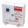
I have the Dayton solid state on timer. I have never used one of these but it looks pretty easy to wire. It's says 1 amp resistive in the specs for it and on the load line on the relay. If it's just powering the two pump contractors in this circuit is this ok or do I need another fuse to protect the solid state timer.

I appreciate the help from whoever replies, I'm new to electronics as you can tell, this is my first time doing any controls, relays, etc.
image.jpeg
 

Bluejets

Oct 5, 2014
6,973
Joined
Oct 5, 2014
Messages
6,973
New circuit diagram and operation of same enclosed below.
 

Attachments

  • Operation of system.pdf
    173.6 KB · Views: 82
  • controls.jpg
    controls.jpg
    54.6 KB · Views: 126

skenn_ie

Sep 7, 2009
33
Joined
Sep 7, 2009
Messages
33
Just buy a heavy duty pressure switch (eBay ?) that has DPDT of contacts. I replaced the little pressure switch on a water pump after it had failed twice. It is quite noisy when is switches, but it is universal and I can get at the contacts to clean them is that is ever necessary. It has adjustable changeover pressure, and adjustable hysteresis.
 

bricklayer

Jun 11, 2016
10
Joined
Jun 11, 2016
Messages
10
Both pumps operate at different high and low pressures. 2 contractors and 2 switches would still be needed. I'm going to go with bluejets design and test it out.
 
Top