Maker Pro
Maker Pro

Dewalt DC012 radio - No sound

Gilles H

Oct 18, 2020
6
Joined
Oct 18, 2020
Messages
6
Hi, I have a Dewalt DC012 radio, no sound anymore. I measure the output voltage of the power pcb assy (which feeds the radio pcb), it is supposed to be 13V, but is 16V (circled in orange on picture).

My question is: could this extra 3V prevent the radio board to function properly?

I did a visual check, iI cannot see anything damaged or burnt on each pcbs, front and back, except for the area behind the resistor (circle in red) where the pcb changed color. The resistor's color bars indicates it is a 15 ohms resistor which measures good. The two blue relays on the left get pretty hot too.

Thank's

Gilles
 

Attachments

  • DC012.jpg
    DC012.jpg
    110.6 KB · Views: 30

Bluejets

Oct 5, 2014
6,958
Joined
Oct 5, 2014
Messages
6,958
Cannot make out anything as photo detail is low.

Are you running on battery or mains supply?

Has the aux port been used?
 
Last edited:

73's de Edd

Aug 21, 2015
3,629
Joined
Aug 21, 2015
Messages
3,629
Sir Gilles H . . . . .

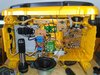
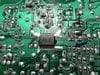
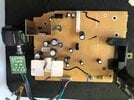
Referring to the resolution limitations being provided by your . . . .DC012.jpg photo.
Your fretting of the relays and hot resistor can be allayed as they are being associated with the tool battery charger portion of the unit.
The sole radio aspects portions are being its power transformer at the right top corner of the speaker frame, then its power board as the one with the fuse and 4 rectifier diodes and storage capacitor(s) being right in line with the top of the speakers central whizzer cone. this is outputted as your mentioned DC voltage supply which routes into your ORANGE circle at the radio PCB.

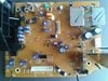
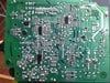
All is being well up to there and then you see where my drawing continues with your same ORANGE circle reference.
Now they may use that full voltage that you are encountering in the supply down at the AUDIO output IC.
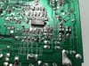
BUT . . . . now investigate to see the corner heat sink and its associated power device. ( YELLOW rectangle mark up in two places. )
Looks like it has a Q4 ? as its assigned designator . . . . . thereby making it a power transistor vice a normally suspected 3 terminal regulator.
See if it is not working in conjunction with the small transistor at its side to make a voltage regulator stage to drop your inputted voltage down to a yet lower level supply voltage.
If so, you will find full voltage on its collector and the reduced / regulated voltage being outputted at its emitter.

Then as per my YELLOW STAR, you probably will find that IC1 device as being a 3 terminal regulator dropping down to a 5V logic supply level.

Supply those parts numberings and we will then sort them out to see whas happening ?


Thaaaaaaaaaaaaassssssssit . . . . .fer now . . .

A MO' BETTAH RADIO CIRCUIT BOARD REFERENCING . . . . .

DC012-Radio-Board.png


https://i.postimg.cc/Q8xYGWGT/DC012-Radio-Board.png


73's de Edd . . . . .

I came home and my dog peed a little because he was s o o o o o happy to see me.
Now, in my thinking about it . . . . . NONE of my friends pee when they see me.
Know whuts ? . . . . . I'm now fully beginning to think that I am being surrounded by fake friends.


.
 

Gilles H

Oct 18, 2020
6
Joined
Oct 18, 2020
Messages
6
Thank you for the replies.

To Bluejets: I plugged in the AUX, no sound neither.

To 73's de Edd: I have limited electronic knowledge, I can only repair the obvious. I cannot identify he big IC with the butterfly heatsink as the heatsink is soldered and would prefer to unsolder as a last resort, If you absolutely need it for the pinout, please let me know.

The small IC (yellow star) has something that looks like '78M08' printed on it. Datasheet: https://www.google.com/url?sa=t&rct...heet/l78.pdf&usg=AOvVaw0L7cc0_wWEocAIvbEOmE50

B1370 datasheet: https://www.web-bcs.com/transistor/tc/b0/B1370.php?lan=en&cl=1

I took closer pictures. Due to the limited information available, please let me know if you find worthed to provide a step by step testing of the suspicious components to find the culprit, I would follow the instructions.

Thank you,

Gilles

Yellow star IC:
2020-10-19 09.50.09.jpg

Yellow star IC close-up:
78M08.jpg

Small yellow rectangle (B1370):
2020-10-19 09.49.14.jpg

Large yellow rectangle solder side:
2020-10-19 09.52.43.jpg
 

Gilles H

Oct 18, 2020
6
Joined
Oct 18, 2020
Messages
6
To Bluejets: sorry, running on main, got no batteries. Thank you, Gilles.
 

shrtrnd

Jan 15, 2010
3,876
Joined
Jan 15, 2010
Messages
3,876
You'll probably get more help from Bluejets and 73s de Edd, I'm just jumping in here to mention the 78M08 is a +8V voltage regulator, and you can check for the voltage on that component while waiting for additional help.
 

Gilles H

Oct 18, 2020
6
Joined
Oct 18, 2020
Messages
6
You'll probably get more help from Bluejets and 73s de Edd, I'm just jumping in here to mention the 78M08 is a +8V voltage regulator, and you can check for the voltage on that component while waiting for additional help.

Thank you for your reply. I measure 11.91V at input and 7.99V at output.

Thank you,

Gilles
 

Gilles H

Oct 18, 2020
6
Joined
Oct 18, 2020
Messages
6
Hi, I noticed that my DC012 PCB is another version than 73's de Edd. Here are more picture if this can help. Thank you, Gilles.
 

Attachments

  • Component side.jpg
    Component side.jpg
    121.3 KB · Views: 18
  • Solder side.jpg
    Solder side.jpg
    184.7 KB · Views: 19
  • 2020-10-20 10.16.37.jpg
    2020-10-20 10.16.37.jpg
    82.1 KB · Views: 18
  • ChipX.jpg
    ChipX.jpg
    148.6 KB · Views: 16
  • ChipY.jpg
    ChipY.jpg
    136.9 KB · Views: 12
  • ChipZ.jpg
    ChipZ.jpg
    136.7 KB · Views: 18

Gilles H

Oct 18, 2020
6
Joined
Oct 18, 2020
Messages
6
Ok, thank's to everyone. Project closed, radio sent to recycling center. Gilles
 

PH5

Feb 2, 2022
1
Joined
Feb 2, 2022
Messages
1
I had a DC012 radio recently that had the same problem. Charger worked, but the radio was completely dead. I measured 18V going into the radio circuit board, but it most of the voltages on the board were very low or zero. For anybody else that is having that problem, I found out that C228 (a big electrolytic capacitor) near the 78M08 voltage regulator had shorted out. When it shorted, it also blew out transistor Q504 near the audio IC, which is involved in voltage regulation. You should have around 12V at the collector and emitter of Q504 if it is working. Neither one of those were obviously damaged to the naked eye, though when I looked really closely at Q504 I could see a slight bulge in it. I don't know for sure what transistor it was originally, but I used a Y2 SS8550 PNP transistor as a replacement and replaced the cap too. It fired up and worked again after I did. Hope that helps anyone else trying to fix theirs.

PH
 

nickels65

Feb 11, 2024
4
Joined
Feb 11, 2024
Messages
4
Cannot make out anything as photo detail is low.

Are you running on battery or mains supply?

Has the aux port been used?
I WAS TRYING TO FIX A DEWALT WORKSITE CHARGER DC012 AND FOUN
I had a DC012 radio recently that had the same problem. Charger worked, but the radio was completely dead. I measured 18V going into the radio circuit board, but it most of the voltages on the board were very low or zero. For anybody else that is having that problem, I found out that C228 (a big electrolytic capacitor) near the 78M08 voltage regulator had shorted out. When it shorted, it also blew out transistor Q504 near the audio IC, which is involved in voltage regulation. You should have around 12V at the collector and emitter of Q504 if it is working. Neither one of those were obviously damaged to the naked eye, though when I looked really closely at Q504 I could see a slight bulge in it. I don't know for sure what transistor it was originally, but I used a Y2 SS8550 PNP transistor as a replacement and replaced the cap too. It fired up and worked again after I did. Hope that helps anyone else trying to fix theirs.

PH
I SAW YOUR INPUT ABOUT A DC012 DEWALT RADIO\CHARGER AND I WAS WONDERING IF YOU HAVE ANY INPUT TO MY SITUATION.
I THINK MY VOLTAGES ARE OK ALTHOUGH I DONT HAVE A SCHEMATIC, BUT ON THE AUDIO IC I DON'T HAVE VOLTAGES ON THE INPUT PINS AND WITH A SEPARATE AMPLIFIER VERY VERY WEAK MUSIC BUT THE OUTPUT PINS 3,11 HAVE GOOD SOUND.I SHOULD ALSO SAY THAT THE SOUND COMES OUT OF THE SPEAKERS OCCASIONALLY AND VERY LOW. IM JUST LEARNING THIS STUFF BUT IWAS HOPING THAT YOU MIGHT HAVE ANY IDEAS,I THINK THAT THE CHIP IS BAD, BUT IM NOT SURE.
YOUR HELP WOULD BE APPRECIATED. THANKS M M
 

H2814D

Nov 4, 2017
215
Joined
Nov 4, 2017
Messages
215
I WAS TRYING TO FIX A DEWALT WORKSITE CHARGER DC012 AND FOUN

I SAW YOUR INPUT ABOUT A DC012 DEWALT RADIO\CHARGER AND I WAS WONDERING IF YOU HAVE ANY INPUT TO MY SITUATION.
I THINK MY VOLTAGES ARE OK ALTHOUGH I DONT HAVE A SCHEMATIC, BUT ON THE AUDIO IC I DON'T HAVE VOLTAGES ON THE INPUT PINS AND WITH A SEPARATE AMPLIFIER VERY VERY WEAK MUSIC BUT THE OUTPUT PINS 3,11 HAVE GOOD SOUND.I SHOULD ALSO SAY THAT THE SOUND COMES OUT OF THE SPEAKERS OCCASIONALLY AND VERY LOW. IM JUST LEARNING THIS STUFF BUT IWAS HOPING THAT YOU MIGHT HAVE ANY IDEAS,I THINK THAT THE CHIP IS BAD, BUT IM NOT SURE.
YOUR HELP WOULD BE APPRECIATED. THANKS M M
You could always try the fix that PH5 reported worked for him. Did you understand which components he replaced? It looks like he replaced one transistor (Q504) and one electrolytic capacitor (C228). You may get lucky with doing the same. The other option includes testing the components on your board for failures.

Just so you know, though, if you are getting some sound out "occasionally," there is a good possibility it may just be that capacitor.
 

nickels65

Feb 11, 2024
4
Joined
Feb 11, 2024
Messages
4
I WAS TRYING TO FIX A DEWALT WORKSITE CHARGER DC012 AND FOUN

I SAW YOUR INPUT ABOUT A DC012 DEWALT RADIO\CHARGER AND I WAS WONDERING IF YOU HAVE ANY INPUT TO MY SITUATION.
I THINK MY VOLTAGES ARE OK ALTHOUGH I DONT HAVE A SCHEMATIC, BUT ON THE AUDIO IC I DON'T HAVE VOLTAGES ON THE INPUT PINS AND WITH A SEPARATE AMPLIFIER VERY VERY WEAK MUSIC BUT THE OUTPUT PINS 3,11 HAVE GOOD SOUND.I SHOULD ALSO SAY THAT THE SOUND COMES OUT OF THE SPEAKERS OCCASIONALLY AND VERY LOW. IM JUST LEARNING THIS STUFF BUT IWAS HOPING THAT YOU MIGHT HAVE ANY IDEAS,I THINK THAT THE CHIP IS BAD, BUT IM NOT SURE.
YOUR HELP WOULD BE APPRECIATED. THANKS M M

You could always try the fix that PH5 reported worked for him. Did you understand which components he replaced? It looks like he replaced one transistor (Q504) and one electrolytic capacitor (C228). You may get lucky with doing the same. The other option includes testing the components on your board for failures.

Just so you know, though, if you are getting some sound out "occasionally," there is a good possibility it may just be that capacitor.
Thank you for your reply I found that the speakers had a bad solder joint on the ground so that fixed my sound to stay on constantly, and after looking at the board i cannot find a c228 or q504 maybe PH5 has a different board, Ill try to see about voltages going into my audio ic I have amplification on the out put pins and voltages but nothing on the input pins, with my separate amplifier I get music on these output pins and transistors going towards the speaker connections ,thanks for your help Im hoping I could find a schematic ,Ill keep looking.
 

H2814D

Nov 4, 2017
215
Joined
Nov 4, 2017
Messages
215
Thank you for your reply I found that the speakers had a bad solder joint on the ground so that fixed my sound to stay on constantly, and after looking at the board i cannot find a c228 or q504 maybe PH5 has a different board, Ill try to see about voltages going into my audio ic I have amplification on the out put pins and voltages but nothing on the input pins, with my separate amplifier I get music on these output pins and transistors going towards the speaker connections ,thanks for your help Im hoping I could find a schematic ,Ill keep looking.
Can you post clear pictures of the front and back of the board. Let us take a look.
 

nickels65

Feb 11, 2024
4
Joined
Feb 11, 2024
Messages
4
Here are some pics I found Z1 to be giving low readings both ways, Im still checking other components, sorry I couldn't point it out to you but i dont have a paint app on my computer but its right above IC 301 (74HC4052).Thanks
 

Attachments

  • IMG_3783.jpeg
    IMG_3783.jpeg
    485.9 KB · Views: 10
  • IMG_3784.jpeg
    IMG_3784.jpeg
    318.3 KB · Views: 10

H2814D

Nov 4, 2017
215
Joined
Nov 4, 2017
Messages
215
Here are some pics I found Z1 to be giving low readings both ways, Im still checking other components, sorry I couldn't point it out to you but i dont have a paint app on my computer but its right above IC 301 (74HC4052).Thanks
Yes. They appear to be entirely different boards. Yours is probably a newer model board with more smd components taking the place of the other through hole components. You will probably have to remove that Zener from the board to get an accurate test. Testing it in circuit is not reliable. I doubt that is the problem though. You should check the electrolytic capacitors first. C715 looks like it has a slight bulge to it. Does it? It may just be the way the photo was taken. You should check each of them for visible signs of failure, but that is not always reliable. You will either have to pull one leg out of the circuit and test them with either a multimeter set on capacitor setting for uF rating, or with an ESR meter (more reliable) you can check them in circuit.
 

nickels65

Feb 11, 2024
4
Joined
Feb 11, 2024
Messages
4
Yes. They appear to be entirely different boards. Yours is probably a newer model board with more smd components taking the place of the other through hole components. You will probably have to remove that Zener from the board to get an accurate test. Testing it in circuit is not reliable. I doubt that is the problem though. You should check the electrolytic capacitors first. C715 looks like it has a slight bulge to it. Does it? It may just be the way the photo was taken. You should check each of them for visible signs of failure, but that is not always reliable. You will either have to pull one leg out of the circuit and test them with either a multimeter set on capacitor setting for uF rating, or with an ESR meter (more reliable) you can check them in circuit.
I visually inspected those caps and they seem fine, tried a few tests with my meter and a cheap esr board I found online but Im not trusting their erratic readings, Im waiting for an air desoldering tool so that I can pull them out to test ,looks like I did find a couple of bad mosfets Q1 and Q2, Q2 was of interest as it is close to the zener diode that checked faulty ,Im having a difficult time getting the #s off these parts all of the writing is gone ..So Im going to wait till I get that tool to unsolder the cap legs and replace what I need.I appreciate your help and hope you will continue to do so.
 

H2814D

Nov 4, 2017
215
Joined
Nov 4, 2017
Messages
215
If you are trying to test those components (caps, mosfets, diodes) while they are still soldered in circuit, you will not always get the proper results. They need to be removed, or partially removed, in order to test them. And again, visual evaluations of electrolytic capacitors is never a good way to check them. There are visual clues when they are bad sometimes, and they are quite obvious, but not always.
 

kellys_eye

Jun 25, 2010
6,514
Joined
Jun 25, 2010
Messages
6,514
You should check the electrolytic capacitors first. C715 looks like it has a slight bulge to it.
Issues such as bulging are generally associated with switched-mode power supplies (caused by HF ripple) and hardly ever with 'analogue' DC versions of equipment unless it is REALLY old.
 

DocOfRock2000

Feb 23, 2024
3
Joined
Feb 23, 2024
Messages
3
I visually inspected those caps and they seem fine, tried a few tests with my meter and a cheap esr board I found online but Im not trusting their erratic readings, Im waiting for an air desoldering tool so that I can pull them out to test ,looks like I did find a couple of bad mosfets Q1 and Q2, Q2 was of interest as it is close to the zener diode that checked faulty ,Im having a difficult time getting the #s off these parts all of the writing is gone ..So Im going to wait till I get that tool to unsolder the cap legs and replace what I need.I appreciate your help and hope you will continue to do so.
Does anybody have a schematic of this board? I have the same failure issue with all caps checking OK, and good voltages everywhere...8, 12, 14, 16, etc.., just really really low volume sound. There's got to be something simple but critical in the audio amplifier input path that affects both channels of audio somehow. The board is too small to visually track audio path. Need schematic. The three pin B1336 heat sink is warm, the 78M08 volt reg is warm and correct in and out voltages, 12 and 8, but the Audio IC501 is cool and with a heat sink fin should feel warm. So I think the problem is here. The output 1000uF capacitors to the speakers are also both good. Any ideas? This common failure has to be a common reason. What a shame, the whole rest of the unit works perfectly, display, buttons, knobs (tuner needed a little electronic spray but that's normal). What the heck here.
 
Top