Maker Pro
Maker Pro

Common Cathode Triple digit display pinmap help!!!

Electrodogs

Nov 3, 2015
14
Joined
Nov 3, 2015
Messages
14
I have a triple common cathode display and I cant do anything with it. I have done 7 segment displays before but this one came with no pin map and i cand find any way to use it I will post a pic bellow
Model:Ark SP400561N
Part numberD5631I
 

Attachments

  • image.jpg
    image.jpg
    67.1 KB · Views: 258
  • image.jpg
    image.jpg
    66.8 KB · Views: 244
  • image.jpg
    image.jpg
    70.2 KB · Views: 240

ramussons

Jun 10, 2014
466
Joined
Jun 10, 2014
Messages
466
Trial and Error is a sure method. Takes time and patience. But can be done.
 

Electrodogs

Nov 3, 2015
14
Joined
Nov 3, 2015
Messages
14
Agreed but I have over 1000 combinations and only about 100 of them would work
 

hevans1944

Hop - AC8NS
Jun 21, 2012
4,889
Joined
Jun 21, 2012
Messages
4,889
Agreed but I have over 1000 combinations and only about 100 of them would work
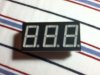
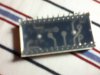
What a crock. From your fuzzy out-of-focus picture it appears there are only 28 pins on the package connecting to 24 segments, including a decimal point for each digit, plus a common cathode for each digit. So, out of 28 pins, 27 are actually used. However, there are many more than 1000 combinations and there is only one that works.

Try using the connections on this image, or visit this web page.

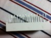
If you can't read the pin numbers (even after blowing the image up large) use the following "trial and error" method to identify the pin connections: solder one end of a 47Ω 1/4 watt resistor to the positive terminal of a "D"-size alkaline cell. You will hold the cell in your hand and use the free end of the resistor as a test probe. Solder about six to ten inches of insulated hook-up wire to the negative terminal of the cell. The free end of that wire will be a second test probe. Together you will use this rig to find all the segment connections and all the common cathode connections. It will take you less than thirty minutes if you are methodical and write everything down.

Touch the free end of the resistor to pin 1 on the display. Touch each of the remaining 27 pins with the free end of the hook-up wire until you find a pin that makes a segment illuminate. Mark that pin as Kn, where n is the digit position and K stands for cathode 1, 2, or 3. Mark the first pin na, nb, nc, nd, ne, nf, ng, or ndp (decimal point) depending on what lit up. Congratulations! You have now found one segment pin and one common cathode pin for one digit!

OTOH, if none of the remaining 27 pins make a segment light up, reverse the leads and repeat the test, again marking the positive lead as na, nb, nc, nd, ne, nf, ng, or ndp depending on which segment lit up. Mark the pin of the negative lead as Kn.

If none of the segments light up with the leads reversed, mark the original first pin you chose as N/C (not connected). Pick another pin and repeat the test until you find a segment that does light up. There should be one N/C pin on the display, so you stand one chance in twenty-eight of finding it on your first try..

There are three common cathode pins, one for each digit of the display. Once you have identified the first common cathode and the digit it is associated with, leave the negative lead of the hook-up wire attached to that pin and find the remaining segments for that digit by touching pins with the free end of the resistor. Once you have found and labeled all the pins associated with a single digit, attach the free end of the resistor to another pin that you have not identified and repeat the first test until you find another common cathode. Leave the free end of the hook-up wire attached to that common cathode and use the free end of the resistor to find the remaining segments for that digit. Finally, connect the free end of the resistor to one of the remaining pins that have not been previously identified and repeat the first test until you find the common cathode for that digit. Leave the negative hook-up wire attached to the common cathode and use the free end of the resistor to find the remaining segments.

Easy peasy once you get the hang of it. The complete test takes only a few minutes to find all the segment connections and the common cathodes. Be sure to write everything down.
 

AnalogKid

Jun 10, 2015
2,904
Joined
Jun 10, 2015
Messages
2,904
I agree with hevans, you're overthinking this. Make a table with 24 lines, one for each pin, and sit down with a power supply, one resistor, and a pencil. Mapping the entire device will tale less than 2 minutes, depending on how fast you can write 1a, 1b, etc. Note that you will be flipping the part over and back many times, so keep track of where pin 1 is and which digit is being activated. To start, clip one lead to a corner pin, and slide the end of the resistor along all the other leads like strumming a guitar. Something should blink. If not, reverse the leads and repeat. This will get you a starting connection. Repeat with each of the other corner pins to get a basic map of where each digit's pins are.

You will find that the pin map is almost exactly the same as three independent 1-digit displays sitting side by side.

ak
 

hevans1944

Hop - AC8NS
Jun 21, 2012
4,889
Joined
Jun 21, 2012
Messages
4,889
Sometimes you luck out and these displays will fit the pin spacing on a solderless breadboard. If so, plug it in so you have access to the pins and the front of the display simultaneously.
 

hevans1944

Hop - AC8NS
Jun 21, 2012
4,889
Joined
Jun 21, 2012
Messages
4,889
... You will find that the pin map is almost exactly the same as three independent 1-digit displays sitting side by side. ...
Yep. Just imagine you have the task of connecting each segment and decimal point and cathode to a pin without crossing any wires. Once you find out where the pins are for one digit the pins for other two should fall right into place. This ain't rocket science, it's just wires. OTOH, if you find yourself with one of those spiffy LCD readouts that accept ASCII serial data streams and scroll characters across its face, that's a whole other problem.
 

Electrodogs

Nov 3, 2015
14
Joined
Nov 3, 2015
Messages
14
thank you for your in depth explanation. I feel like an idiot for posting it now because I feel I have gotten better at electronics now. But I seriously needed an answer back then I really wanted to get it to work.

By the way I displayed HI using logic gates on one of those ASCII LCD's though Arduino makes it much easier.
 

(*steve*)

¡sǝpodᴉʇuɐ ǝɥʇ ɹɐǝɥd
Moderator
Jan 21, 2010
25,510
Joined
Jan 21, 2010
Messages
25,510
It wasn't a silly question. You just didn't know the easy way to do it.

By the way, I use my multimeter on the diode test range to figure out the connections. With a bit of practice, the longest part is writing down what each pin does.

Good to hear you have the LCD driving stuff figured out too.
 
Last edited:

hevans1944

Hop - AC8NS
Jun 21, 2012
4,889
Joined
Jun 21, 2012
Messages
4,889
Wow! You have been making progress! Years ago, the pin-outs of LED displays had me stonkered for awhile too... until I finally realized that they HAD to be manufactured in a simple way that connected each segment to each package pin WITHOUT crossing any wires. This was years before anyone was routinely using multilayer circuit boards to connect anything, but I believe multi-digit LED displays are still made the same way today.

I bought a touch-screen color LCD display shield for my Arduino Uno at Radio Shack (well, I think it's got touch-screen capability) a few years ago, but I am not even close to learning how to use it. Too many other fish to fry right now. So congratulations on learning how to make your ASCII LCD display say "HI" using logic gates! And, yes, I suppose it will be easier with Arduino when I find my "round tuit" and actually do it.

As Steve said, there is no such thing as a silly question here, although the quality of the answers vary.

And by the way, since I missed it when you posted your first question here: Welcome to Electronics Point! And welcome back, too!
 
Top