Maker Pro
Maker Pro

Building a linear 5v 5a powersupply for Raspberry pi streamer build.

thelad73

Mar 5, 2024
8
Joined
Mar 5, 2024
Messages
8
Hi, first post so be gentle please.
I over speced my first design so went back to the drawing board and did some more reading
so now I'm looking at a toroidal with two secondary outputs at 6v 4.4a each. now if my maths is correct it should be(in parallel) 8.484v and 8.8a into the recitifier. after the rectifier bridge my maths says 7.284v and 8.8a then into 2 4700uf 16v caps(in parallel)then into the ldo regulator which outputs 5v 5a it says. Then the 2 caps again and a bleeder resistor 1k 5w(parallel)
so first question is this ok or needs changes
is the voltage change from 7.2 to 5 on the regulator too much and create a massive amount of heat?
i do have other questions but no point asking if this circuit is rubbish and dangerous
cheers
 
Last edited:
Martaine2005

May 12, 2015
4,953
Joined
May 12, 2015
Messages
4,953
Hi, what maths are you using?
2 x 6V in parallel is 6V.

7.2V input for a LDO 5V regulator should be fine but what does the data sheet say as you haven’t supplied any part numbers.

Is the transformer centre tapped?
It should have a label on it?.

Martin
 

thelad73

Mar 5, 2024
8
Joined
Mar 5, 2024
Messages
8
hi i'll get the parts list. I mucked up my post. I meant 7.2v dc after rectification and caps before the regulator. but i'm questioning that now. 6x1.414 is 8.5v near enough but i thought there would be a voltage loss of around 1.2v after rectification.
Yeah I do know parallel secondary doesn't increase voltage but adds the current of the 2 outs(not being rude but just wanted you to know even as a newb i have some basics;))
like i said i'll post up parts list and hopefully that helps me learn this
cheers
 

bertus

Moderator
Nov 8, 2019
3,330
Joined
Nov 8, 2019
Messages
3,330
Hello,

How did you connect the transformer?
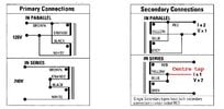
There are two ways to use the two secondary outputs.
This picture shows the possibilities from an ILP datasheet:
ILP_connections.jpg
I have drawn the centre tap in the bottom picture.

Bertus
 

Attachments

  • transformers_mains.pdf
    192.4 KB · Views: 0

thelad73

Mar 5, 2024
8
Joined
Mar 5, 2024
Messages
8
hi parts list for you to peruse and help with if you don't mind
The Regulator https://uk.rs-online.com/web/p/volt...K-CJAFF-_-digipart.com-_-RS RS Components UK
The rectifier is this https://www.mouser.co.uk/ProductDet...2YY1oM2H-Ernl3Z3gU1klU1ESLHWl4DhoC_MwQAvD_BwE
The caps are these PANASONIC ECA1CHG472 I now get the feeling the voltage is far too low on them
and the resistor for the bleed after power off is this NEOHM - TE CONNECTIVITY EP5WS1K0J

the transformer was a 12v so i realised after some research that would burn the the regulator without a heat sink the size of a phone book.
all these are set to be returned and i'm going to start again
 

Harald Kapp

Moderator
Moderator
Nov 17, 2011
13,747
Joined
Nov 17, 2011
Messages
13,747
Your' mixing up a few things and your math is thence only partly correct.
As per @Martaine2005 's post: 2 × 6 V in parallel is still 6 V. RMS that is in in this case.
The 8.48 V are the peak value of the sine.
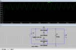
After the rectifier you have 7.28 V peak. The capacitor(s) is charged to this peak value. Then it will be discharged by the load current. AT 5 A load current the capacitor will never be fully charged:
1711287977368.png

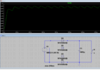
Even at only 1 A load current there is still considerable ripple:
1711288037540.png
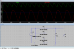
Using "better" diodes and 10 mF (yes, that'S milliFarad) we get:
1711288271653.png
Still 3 V ripple, dropping the outpuit voltage to under 5 V. No LDO can make 5 V from this.

Before using an unreaonably large capacitor, use another transformer with a higher output voltage.

is the voltage change from 7.2 to 5 on the regulator too much and create a massive amount of heat?
Assuming you resolve the first issue and provide sufficient input voltae to the linear regulator, assuming further a minimum voltage drop of 1 V between input and output of the regulator (see the datasheet), we get 5 W power dissipation. Possibly manageable, depending on the regulator and the cooling you can provide (heatsink).


The better solution is a switch mode power supply, however.
 
Last edited:

thelad73

Mar 5, 2024
8
Joined
Mar 5, 2024
Messages
8
Hello,

How did you connect the transformer?
There are two ways to use the two secondary outputs.
This picture shows the possibilities from an ILP datasheet:
View attachment 63149
I have drawn the centre tap in the bottom picture.

Bertus
nothing has been built yet, i'm sending the compents back and restarting. i'm just looking for 230v 2 input wires and something that can out 6v and give me at least 7 amps be it the 2 secondarys in parallel or a single output on the secondary
 

bertus

Moderator
Nov 8, 2019
3,330
Joined
Nov 8, 2019
Messages
3,330
Hello,

You might want to read the attached PDF about rectifiers and buffer capacitors.

Bertus
 

Attachments

  • Unit12.pdf
    788.3 KB · Views: 1

thelad73

Mar 5, 2024
8
Joined
Mar 5, 2024
Messages
8
Your' mixing up a few things and your math is thence only partly correct.
As per @Martaine2005 's post: 2 × 6 V in parallel is still 6 V. RMS that is in in this case.
The 8.48 V are the peak value of the sine.
After the rectifier you have 7.28 V peak. The capacitor(s) is charged to this peak value. Then it will be discharged by the load current. AT 5 A load current the capacitor will never be fully charged:
View attachment 63151

Even at only 1 A load current there is still considerable ripple:
cheers for that. I have explained i do understand that parallel on the secondary doesn't increase the voltage, just want to point this out as i think it sounded like i believed the parallel was leading to the voltage increase. so my maths even if a bit muddled was actually correct with the voltage going into the regulator, or near enough? my calculations were output voltage 6x1.414 then subtract the diode voltage drop, my rectifier says 1.1 but i used 1.2.
 

davenn

Moderator
Sep 5, 2009
14,265
Joined
Sep 5, 2009
Messages
14,265
but i'm questioning that now. 6x1.414 is 8.5v near enough but i thought there would be a voltage loss of around 1.2v after rectification.
Yeah I do know parallel secondary doesn't increase voltage but adds the current of the 2 outs(not being rud

where did you get 6 x 1.414 ??
Then the 2 caps again and a bleeder resistor 1k 5w(parallel)

that's only 500 Ohms way way too low even just a single1k is almost too low ... try 10k instead as a better valur
 

Delta Prime

Jul 29, 2020
1,985
Joined
Jul 29, 2020
Messages
1,985
I'm the only one capable of helping you here that is...
Hi, first post so be gentle please
Gentle enough for you?
You just went through the gauntlet now you're mine. Welcome to the family. May I ask?
What version raspberry pi?
I asked because that will dictate the streaming endpoint capability of supporting high-resolution PCM, FLAC, DSD, and even MQA files (if supported by your DAC). How good can it sound? That depends more on your DAC’s capabilities and sonics than on the Pi itself. And if you want to go “ultra-fi” there are power supply and SPDIF upgrades for the Pi that claim an even higher level of performance.
It seems no one here is capable of helping you.
Except me..
 

Harald Kapp

Moderator
Moderator
Nov 17, 2011
13,747
Joined
Nov 17, 2011
Messages
13,747
my maths even if a bit muddled was actually correct
Your math may be correct, but the way you presented it has us confounded, as you stated
two secondary outputs at 6v 4.4a each. now if my maths is correct it should be(in parallel) 8.484v
Which makes no sense. Nowhere did you indicate that the 6 V are rms and the 8.484 V are peak. This we had to deduce, as i did in post #6.

It will be a big help when you state details clearly. People tend to forget (more or less important) details because these seem obvious to them while they are working on a project. But remember that the other forum members are not deeply involved in your project and need these details to understand the issue(s) at hand.
 
Top