Maker Pro
Maker Pro

Buffer to delay a signal

Lizwi

Nov 9, 2023
4
Joined
Nov 9, 2023
Messages
4
Hi

I am simulating a delay line time to digital converter, I have been able to simulate a counter TDC,

How do I create a buffer with delay in Verilog HDL? I am trying to simulate what is in the attachment. Please help.
 

Attachments

  • Tapped-delay-line-TDC.png
    Tapped-delay-line-TDC.png
    10.1 KB · Views: 5

Lizwi

Nov 9, 2023
4
Joined
Nov 9, 2023
Messages
4
What am I doing wrong here, I want to get a pattern on the timing diagram attached. The buffers are there but they don't seem to delay the signal.
 

Attachments

  • Capture.PNG
    Capture.PNG
    29.4 KB · Views: 6
  • Capture2.PNG
    Capture2.PNG
    76.7 KB · Views: 7
  • Capture3.PNG
    Capture3.PNG
    15.2 KB · Views: 6

Harald Kapp

Moderator
Moderator
Nov 17, 2011
13,748
Joined
Nov 17, 2011
Messages
13,748
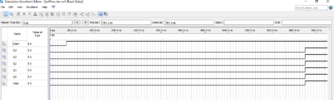
You need to zoom in much more into this area:
1709056513281.png
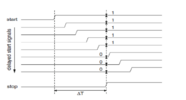
The buffers in your simulation probably have a delay in the sub-ns range. The dashed lines are 10 ns apart. You can't see the small delay in that resolution.

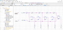
Another possibility is that the RTL compiler "optimizes" the design, recognizing that the output signals of the buffers are identical and therefore removes the buffers from the simulation. You may (or may not) have an option to turn off such an optimization in the simulator's settings.

Note that in a real circuit the delay may vary considerably depending on where on the chip the buffers are palced and how long the interconnects are.
 
Top