First off, I want to say I'm sorry for the long delay - I didn't want you guys to think that I didn't appreciate all your help. I just wasn't able to work on this project for a while. But, I finally did yesterday. I appreciate everyone's replies so I thank you for that. I wish I had half the knowledge/experience you all have individually. Honestly, a lot of things you guys were saying went over my head. Thankfully, one of the first and easier things to check ended up being the culprit!
What was it?
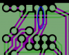
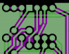
R1 and R2 weren't connected on the PCB as they should have been! One of the images below show the little jumper wire I used (came from an individual wire of a CatV cable) to fix it. The other image shows (on a different PCB that I just soldered all the parts on it yesterday) how I just connected the 2 resistor's leads when I was soldering the components on.
If there is something wrong with the way I did the 'fix', by all means, let me know. I don't know what's best practice or bad practice.
So I tried testing for continuity on my 2 remaining unpopulated PCBs (before I soldered up the 2nd one) and there was no continuity between R1 and R2. I'm not sure where that connection between R1 and R2 was lost/messed up because obviously his schematic is correct.
The Fritzing files are linked to on his site, but here's the direct links to them here since 'bob monsen' requested it:
http://www.dudley.nu/projects/brake_light_blinker/brake_blinker_1.fzz ('design' file)
http://www.dudley.nu/projects/brake_light_blinker/brake_blinker_1.zip (board files)
Again, thank you everyone so much! And I have to give [73's de Edd] an extra thank you since his post was the one that directly helped me to solve/fix it.


")