Maker Pro
Maker Pro

7815/7915 Power Supply Issue

acsww4

May 4, 2017
8
Joined
May 4, 2017
Messages
8
Ladies and gents,

Please let me preface this by stating that I have a novice to average electronics knowledge-base. Now, I am building a Minimoog analog synth from scratch and have slowly but surely hit every roadblock known to man when it comes it troubleshooting (it's probably good for me). So right now, I am working on the MIDI2CV interface with its own dedicated +/- 15v PS and it is based on a standard 78xx/79xx circuit. Now, the issue is that at zero load (yes it has a few LEDs that act as a load) the PS shows a nice +/-15v respective to their individual rails. However with the MIDI2CV unit connected, I get +16v on the positive rail and -2.4v on the negative rail. I am using a 36vct 0.7A transformer with the dual secondaries wired in series. That gives me +22.5v and -22.5v pre-filter cap. Mind you, the MIDI2CV board has never been powered and everything was brand new before powering up the board. Also, the orientation of all the components is correct as I triple checked. WHAT DO I NEED TO DO TO MAKE THIS WORK?!!??!!?!? All kidding aside, please help.

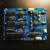
The MIDI2CV interface is shown here: https://midisizer.com/midi2cv-mk2/

With gratitude,

Adam
 

davenn

Moderator
Sep 5, 2009
14,267
Joined
Sep 5, 2009
Messages
14,267
Hi there
welcome to EP :)


. Also, the orientation of all the components is correct as I triple checked. .

I would be really surprised if they are .... you fault symptoms indicate otherwise


WHAT DO I NEED TO DO TO MAKE THIS WORK?!!??!!?!? All kidding aside, please help.

well you haven't shown us any of the important stuff .... namely this power supply
lets see your circuit and a photo or two of its construction


Dave
 

duke37

Jan 9, 2011
5,364
Joined
Jan 9, 2011
Messages
5,364
It sounds as if you do not have a good common connection. If the +15V load is the same as the -15V load, then the common will sit in the middle and all looks well.
If the loads differ, the common gets pulled to one side. I do not understand why you get a total of 18.4V rather than 30V.

Can you put a resistor, say 10Ω, in each of the supplies to see if one side is limited to 1A or so by the regulators.
 

acsww4

May 4, 2017
8
Joined
May 4, 2017
Messages
8
Thank you for the replies. I will take a picture of everything when I return home from work. But your guess on the common ground is exactly what I was thinking, but the 18.4V threw me a curve. Thank you again!
 

acsww4

May 4, 2017
8
Joined
May 4, 2017
Messages
8
So it turns out that my power supply is not the culprit. On the board I am supplying power to, there is a voltage reference chip (LT1021) that had shorted the DNC pins to the ground pin. That is only part of the issue. After removing that chip, there is still a short to ground on the poitive rail. My negative rail is reading a beautiful 15.000v. The positive rail is still reading about 3v. I don't even know where to start...
 

acsww4

May 4, 2017
8
Joined
May 4, 2017
Messages
8
Oh, this is after rebuilding the +/-15v PS. I have verified that the same symptoms appear with a bench power supply as well.
 

Harald Kapp

Moderator
Moderator
Nov 17, 2011
13,747
Joined
Nov 17, 2011
Messages
13,747
Obviously there is still too high a current flowing in the positive rail which drives the positive regulator into current limiting mode and thus reduces the output voltage. Regardless of the power supply used.

You'll have to locate and repair teh short on the power rail. Look for any visual defects (solder blobs etc.).Check the orientation of all polarized components (diodes, transistors, electrolytic capacitors etc.).
If all that doesn't lead to the cause, remove components one by one and measure after each component has been removed.
 

acsww4

May 4, 2017
8
Joined
May 4, 2017
Messages
8
Well... I checked the on-board regulators (317,317,78l05) and they were the cause of my headache. I had them cinched down to the PCB. They were nearly flush with the board. SOOOOOOOO, that is what was causing my short; a few of the pins touching per each reg.
 

Harald Kapp

Moderator
Moderator
Nov 17, 2011
13,747
Joined
Nov 17, 2011
Messages
13,747
I recommend you use new ics as replacements. You never know what internal damage these regulators may have suffered. Even if it looks o.k. for now, in the long term they may fail prematurely.
 

acsww4

May 4, 2017
8
Joined
May 4, 2017
Messages
8
That is exactly what I have done: ordered new ones. Also, I have ordered a new 1021 vref as well because that one I think was actually fried.
 

Nicholas Schlensky

Oct 7, 2015
9
Joined
Oct 7, 2015
Messages
9
Don't forget to insulate the tabs if they are not ground. Many packages have the power tab at a non zero voltage. Don't forget the insulating washers!
 
Top