Hello all,
this is my very first post to this forum and I hope ask my questions in the correct section.
I'm trying to implement an electronic switch with an IGBT controlled by an ESP32 logic (3.3V GPIO). The IGBT acts like a static switch which stays on for a very long time (permanent) - no PWM or something else.
The load is a solar charge controller (SCC) and the power source are PV modules. None of the PV+ and PV- lines are ground connected (floating SCC design). The IGBT should switch up to 500VDC with up to 15A. For other reasons, the IGBT should switch the PV+ line so I think I need a high side driver.
On top of that, all components should be able to run with 3.3V power supply - if possible.
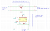
I found a high side driver which seems to be able to be running with Vcc=3.3V power supply (but not 100% sure). Because of using the IGBT in a static mode (permanently switched on), I think I need an external charge pump on top of the high side gate driver itself. So far I came up with the following idea with an IR2125:

I found a charge pump example in a spec which looks like this:

Now I'm not really sure, if I really can use this example because my negative load side is NOT connected to ground (it's floating). But in the example, the negative side of the load is connected with ground and the negative side of the load is connected via a 100k resistor to the ground of the timer - I'm pretty sure this is not what I want to have, because it's a floating load.
So I left with a couple of questions:
1) How to use a charge pump (with a CMOS timer LMC555CN instead of ICM755 given in the example, to be able to run it with Vcc=3.3V) to drive a floating IGBT without ground reference?
2) Will Vcc=3.3V be high enough to drive the IGBT at all. Even if the IR2125 and the LMC555CN would be able to run with Vcc=3.3V, will it be enough voltage to bring the IGBT to switch on? Or do I need at least Vcc=10V-20V to provide high enough gate voltage? I don't know how the boot capacitor and the charge pump would be able to lift the gate voltage to the required level even with a low Vcc?
3) Maybe there are better ideas how to implement such an electronic switch?
Thanks in advance for your help!
Frank
this is my very first post to this forum and I hope ask my questions in the correct section.
I'm trying to implement an electronic switch with an IGBT controlled by an ESP32 logic (3.3V GPIO). The IGBT acts like a static switch which stays on for a very long time (permanent) - no PWM or something else.
The load is a solar charge controller (SCC) and the power source are PV modules. None of the PV+ and PV- lines are ground connected (floating SCC design). The IGBT should switch up to 500VDC with up to 15A. For other reasons, the IGBT should switch the PV+ line so I think I need a high side driver.
On top of that, all components should be able to run with 3.3V power supply - if possible.
I found a high side driver which seems to be able to be running with Vcc=3.3V power supply (but not 100% sure). Because of using the IGBT in a static mode (permanently switched on), I think I need an external charge pump on top of the high side gate driver itself. So far I came up with the following idea with an IR2125:

I found a charge pump example in a spec which looks like this:

Now I'm not really sure, if I really can use this example because my negative load side is NOT connected to ground (it's floating). But in the example, the negative side of the load is connected with ground and the negative side of the load is connected via a 100k resistor to the ground of the timer - I'm pretty sure this is not what I want to have, because it's a floating load.
So I left with a couple of questions:
1) How to use a charge pump (with a CMOS timer LMC555CN instead of ICM755 given in the example, to be able to run it with Vcc=3.3V) to drive a floating IGBT without ground reference?
2) Will Vcc=3.3V be high enough to drive the IGBT at all. Even if the IR2125 and the LMC555CN would be able to run with Vcc=3.3V, will it be enough voltage to bring the IGBT to switch on? Or do I need at least Vcc=10V-20V to provide high enough gate voltage? I don't know how the boot capacitor and the charge pump would be able to lift the gate voltage to the required level even with a low Vcc?
3) Maybe there are better ideas how to implement such an electronic switch?
Thanks in advance for your help!
Frank
