Maker Pro
Maker Pro

MOSFET circuit for latch to enable switching 12 V battery power by micro-controller.

Tech500

Feb 16, 2023
5
Joined
Feb 16, 2023
Messages
5
Trying to keep current required by MOSFET low. Requesting help with a MOSFET latching schmatic and selecting MOSFET. Micro-controller operates at 3.3 Volts. Will be switching 12 Volt DC. 12 Volt is supplied to a step-down buck converter for 5 Volts powering the video camera.

Have coded ESP32 to utilize EByte. E220 module to wake by WOR (Wake on Radio) both receiver and ESP32 from deep sleep, this will occur by URL request and has a low daily occurence of requests.

William
 
Last edited:
Harald Kapp

Moderator
Moderator
Nov 17, 2011
13,756
Joined
Nov 17, 2011
Messages
13,756
Welcome to our forum.

How about a schematic? Your description leaves room for interpretation. We like to know what's going on.
 

Tech500

Feb 16, 2023
5
Joined
Feb 16, 2023
Messages
5
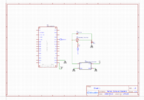
Screenshot 2024-04-12 035411.png

Trying to come up with a switch that will stay on until toggled by a a digital HIGH or LOW. Will be switching 12 volt input to a 5 volt output buck converter.

William
 

Harald Kapp

Moderator
Moderator
Nov 17, 2011
13,756
Joined
Nov 17, 2011
Messages
13,756
This won't work for several reasons.


A high level from the controller will be 5 V max.
5 V on the gate of the MOSFET is still 7V less than the source voltage which is at 12 V. Thus the MOSFET wil be ON!
You'll need a level shifter to control the gate of teh MOSFET with a 12 V volateg for turning it OFF. See e.g. figure 4 on this website.

The next error is D1. As shown in your schematic it will be conducting continuosly, thus making the MOSFET moot. This diode is completely unnecessary, remove it.

Last not least you can't use an N-MOSFET to switch the high side (not unless you use a dedicated high side driver). Typically in your setup you'd use a P-MOSFET (cf. figure 4 as linked before).
 

crutschow

May 7, 2021
856
Joined
May 7, 2021
Messages
856
come up with a switch that will stay on until toggled by a a digital HIGH or LOW.
So is that a momentary or steady digital signal?
Can it be either a high or low signal as needed?
Is it the same digital signal or two separate digital signals?
 

Tech500

Feb 16, 2023
5
Joined
Feb 16, 2023
Messages
5
So is that a momentary or steady digital signal?
Can it be either a high or low signal as needed?
Is it the same digital signal or two separate digital signals?
Digital signal will be momentary; a delay after the digitalWrite, digitalWrite can be either HIGH or LOW as needed.
Two digitalWrite's one to turn on; the other to turn off.

I was wrong MOSFET circuit will be switching 5 Volts; not the 12 Volt battery that is supplying the buck converter providing 5 Volts, which is the camera operating voltage or would I be better off swithing the 12 volts? I think I would be wasting battery power in the buck converter.

William
 
Last edited:

crutschow

May 7, 2021
856
Joined
May 7, 2021
Messages
856
Digital signal will be momentary; a delay after the digitalWrite, digitalWrite can be either HIGH or LOW as needed.
Two digitalWrite's one to turn on; the other to turn off.
would I be better off swithing the 12 volts?
I suggest switching the 12V, as that would eliminate any quiescent power taken by the converter supply with no output load.

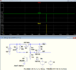
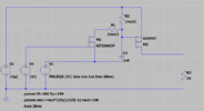
Below is the LTspice sim of a high-side P-MOSFET / BJT latching switch that should do what you want:
It requires a positive going (0V to 3V) pulse to turn on, and a negative going (3V to 0V) pulse to turn off, which you said you can provide.
The pulse width should be ≥10ms.
The P-MOSFET can be just about any that has a low enough on-resistance to carry the converter current with acceptable voltage drop and power dissipation.

1713163589570.png
 
Last edited:

Tech500

Feb 16, 2023
5
Joined
Feb 16, 2023
Messages
5
I suggest switching the 12V, as that would eliminate any quiescent power taken by the converter supply with no output load.

Below is the LTspice sim of a high-side P-MOSFET / BJT latching switch that should do what you want:
It requires a positive going (0V to 3V) pulse to turn on, and a negative going (3V to 0V) pulse to turn off, which you said you can provide.
The pulse width should be ≥10ms.
The P-MOSFET can be just about any that has a low enough on-resistance to carry the converter current with acceptable voltage drop and power dissipation.

View attachment 63361
Thank you crutschow;appreciate your time and knowlege in answering.

William

 
Top