-
Categories
-
Platforms
-
Content
You are using an out of date browser. It may not display this or other websites correctly.
You should upgrade or use an alternative browser.
You should upgrade or use an alternative browser.
Sallen Key Low Pass Filter, bandpass filter
- Thread starter Maglatron
- Start date
Scroll to continue with content
- Joined
- Nov 17, 2011
- Messages
- 13,756
That would be so much easier if you wouldn't put each sentence in a post of its own ...I'm going to go and read back through the thread, see if I can find answers
Hello,
Yes, the (-) goes to the GND and the (+) goes to the MIC.
Bertus
okay sorry for that! going through it now and im on page 12That would be so much easier if you wouldn't put each sentence in a post of its own ...
kellys_eye
- Jun 25, 2010
- 6,514
- Joined
- Jun 25, 2010
- Messages
- 6,514
Got any part of this built and working yet?
700+ posts in this thread............
700+ posts in this thread............
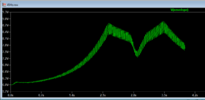
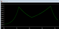
so I have finnished reading the entire thead, I made a start I soldered the bar graph leds on but nothing else yet! kinda got side tracked with another project! I'm back to this now though! thanks! as you can see the 45Hz image uses a 15k resistor for R23 and the 7000Hz uses 820k I want the resistor to be the same value which value would you choose? thanks also can't get the envelope detector working again?
7000Hz
View attachment 62943
7000Hz

45Hz

7000Hz
View attachment 62943
7000Hz

45Hz

Mr Bertus maybe? you were good with this last time! I have refreshed myself with the details today but a little stuck, thanks last time you also changed the R12 from 42.2r to 42.2k aswell and I remember that making it work better!
Last edited:
Martaine2005
- May 12, 2015
- 4,956
- Joined
- May 12, 2015
- Messages
- 4,956
Didn’t you take notes (written)?.
Bad move.
This is not a telephone conversation with forum members.
Read the thread again! All the information is there.
If Mr Bertus remembers, I’m sure he’ll reply, but if not, it’s up to you to find that information that has also been told to you more than twice.
Bad move.
This is not a telephone conversation with forum members.
Read the thread again! All the information is there.
If Mr Bertus remembers, I’m sure he’ll reply, but if not, it’s up to you to find that information that has also been told to you more than twice.
ok getting somewhere
running the 45Hz now... and it reaches similar voltages!!!


Hello,
When pin 8 is gounded the reference voltage will be about 1.25 Volts.
When pin8 is lifted with a resistor, the reference voltage will be higher.
Have a look at the formulas again.
Bertus
Hello,
Why do you want such high values?
Audio is not so high.
The 2.4 volts range is already quite high.
You might even need an amplifier between the filter and rectifier.
Bertus
Hello,
In stead of making a complete series of filters twice, you could add a simple amplifier between the filter and rectifier circuit:
View attachment 61950
That would save you a lot of work.
Bertus
I changed the R23 resistor to 1meg and on the 7000Hz circuit the signal reaches 8.7v at the top and 6 at the bottom so this is good, now waiting for the program to run and I will screen shot it and do the same for the 45Hz one too!Hello,
Now you have R13 at 4K7 and R23 at 165K.
Change that to R13 at 27K and R23 to 1Meg and see what happens with 45 Hz and 7000 Hz.
With those values C14 will have a factor of 6 less influence on the frequency dependend gain.
Bertus
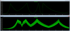
running the 45Hz now... and it reaches similar voltages!!!


yes I took notes when reading it back through it on paper and I'm getting there it was a couple of months back will remember to take notes in future!!! thanks
Didn’t you take notes (written)?.
Bad move.
This is not a telephone conversation with forum members.
Read the thread again! All the information is there.
If Mr Bertus remembers, I’m sure he’ll reply, but if not, it’s up to you to find that information that has also been told to you more than twice.
kellys_eye
- Jun 25, 2010
- 6,514
- Joined
- Jun 25, 2010
- Messages
- 6,514
There's 'bugger all' to the basic design of the filter section that couldn't be actually, physically constructed (on protoboard or hardwired) with sockets for the relevant resistor/capacitor values and you could play to your hearts content until you found something that worked.
How about building ONE channel that actually works?
It would be a damned sight quicker than a 700+ post regime and save some members time too.
It would also be nice for those who have taken the time and effort to assist in this thread to see something PRACTICAL from all their input. A few displays on some board doesn't cut it.
And if you haven't got a grasp of it by now then you need to reconsider your approach.
Similar threads
- Replies
- 9
- Views
- 2K
- Replies
- 1
- Views
- 1K
- Replies
- 7
- Views
- 2K
- Replies
- 1
- Views
- 2K


