Maker Pro
Maker Pro

Help to identify markings in schematics

Evaldas22

Oct 3, 2017
12
Joined
Oct 3, 2017
Messages
12
Hello, guys, I'm a beginner electronic hobbyist and today I tried to fix my home theater subwoofer. Somehow I managed to find the schematic for it. As I begin to read it, to find where certain voltages should be, so I could poke around with DMM, I found some markings that actually got me confused. I'm attaching some photos where I marked all of those markings which got me confused and ask you guys - can you please tell me what they mean and actually help me understand them??
 

Attachments

  • 1.png
    1.png
    20 KB · Views: 96
  • 2.png
    2.png
    57.2 KB · Views: 112
  • 3.png
    3.png
    152.8 KB · Views: 122

shrtrnd

Jan 15, 2010
3,876
Joined
Jan 15, 2010
Messages
3,876
Check the 'Resources' section of this forum for lots of good information.
First photo is of an arrow directing you to find the corresponding connection (the label above the arrow) elsewhere
in the schematic. They just do that so they don't have to draw a lot of crossing and interconnecting lines all over the drawing.
Same thing on the second dwg. Just look for the corresponding input arrow with the same header above it.
Sometimes they may not be on the same page if it's a multi-page schematic.
Looks like the same deal with the third photo.

If I didn't explain this well enough, just ask and somebody here will clarify.
 

Minder

Apr 24, 2015
3,478
Joined
Apr 24, 2015
Messages
3,478
I think what you are referring to is commonly known as Global Labels, rather than clutter a drawing up with a multitude of connections, local labels are defined that match the same label elsewhere in the drawing, as though they were connected.
M.
 

Evaldas22

Oct 3, 2017
12
Joined
Oct 3, 2017
Messages
12
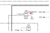
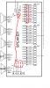
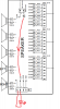
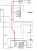
Well, now it's a bit clearer but still how do I know if the signal goes in or out of that pin. I will explain an example of this question. In the first photo, you see a socket(1908). One of the pin is ground and other labeled "STBYLEDSUP". This plug is connected to "SPEAKER board" through the ribbon cable into another socket(1505). Now it seems that label changed from STBYLEDSUP to LED. I see it point away from that socket, so does that mean that the signal will go to somewhere with LED label? To be accurate I'm guessing that the signal will go to socket(1502) on the same speaker board. And on this socket, again, arrow but not pointing into a socket, so how do I understand that?
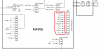
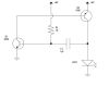
Also going back to 1908 socket. 1 and second photos are from wiring diagram. As I scrolled down I found circuit diagrams. In there I found the same 1908 socket(3rd photo). I see that STBYLEDSUP contains of two branches. So this is how I undestand all this situation. +12v and +5,6v comes to 1908 socket pin throug diodes and resistors(drop voltage I guess). Then, through flat cable it goes to 1505 socket. Then out of it through traces goes to 1502 and from there through couple of wires into actual LED??
The part which still confuses me is those arrows direction. In 1908 is points outwards, but in 1502 inwards. Also in 3rd photo in the right you see the same socket but some arrows are empty(not filled), and pointing out or in.
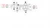
Adding one more photo whith various types of arrows that confuses me.
 

Attachments

  • 4.png
    4.png
    59 KB · Views: 87

Evaldas22

Oct 3, 2017
12
Joined
Oct 3, 2017
Messages
12
usually goes in the direction of the arrow
If so, then why these arrows are pointing in different directions?
And still, need clarification on my given example :(
 

Attachments

  • 5.png
    5.png
    15 KB · Views: 92
  • 6.png
    6.png
    18.9 KB · Views: 91

(*steve*)

¡sǝpodᴉʇuɐ ǝɥʇ ɹɐǝɥd
Moderator
Jan 21, 2010
25,510
Joined
Jan 21, 2010
Messages
25,510
If it points away from the wire it's connected to then it's an output. If it points into the wire it's connected to then it's an input.
 

kellys_eye

Jun 25, 2010
6,514
Joined
Jun 25, 2010
Messages
6,514
...and if it points BOTH ways it's a bi-directional signal (usually a data line).

The problem with schematics is that there are a number of international standards that can be used - ANSI, IEC, BS (British Standard) and IEEE. You can get the actual specifications of those standards to see the details but after 40+ years of engineering I've never yet read one of them!

It boils down to familiarisation really - it just takes some time and a little common sense to figure out what the draughtsman means by his interpretation of the standard(s) used - it's quite common to see a mix of standards in some schematics.

The 'worst' schematics I've come across are invariably for vehicle electrics whilst the best were done by the professional equipment designers of yesteryear. I say this because today's manufacturers have little interest in producing schematics either for intellectual property rights reasons or simply that it's an expense they could do without.

The professionals have (had?) dedicated staff and departments for the purpose of technical literature and the manuals they produced were geek porn to read.... but modern stuff has, at best, a copy of the designers own schematic notes with little else added (circuit descriptions etc).

Time and experience have no substitute so don't expect to be 100% proficient in schematic reading/understanding without a few years of doing so hands-on.
 
Last edited:

Evaldas22

Oct 3, 2017
12
Joined
Oct 3, 2017
Messages
12
Ok, so I will try to analyze one example from the same circuit in the 7th photo attached here. From MAINS board +SEC_AC and -SEC_AC will go to REGULATOR board into DIPMATE 1301. There it will be converted to +12v_A and -12V_A and will go into 1304 socket. Then, from that socket, it will go to back to MAINS board??? There I see 0705 which tells that +12V_A and -12V_A must go into it (not from it?? Thought it came into it from 1304). So in this part, I'm a bit confused. I will attach each of those sockets circuit diagrams and maybe they will help you explain to me.
 

Attachments

  • 7.png
    7.png
    100.5 KB · Views: 94
  • 8.png
    8.png
    23.6 KB · Views: 98
  • 9.png
    9.png
    66.7 KB · Views: 81
  • 10.png
    10.png
    13.6 KB · Views: 100

(*steve*)

¡sǝpodᴉʇuɐ ǝɥʇ ɹɐǝɥd
Moderator
Jan 21, 2010
25,510
Joined
Jan 21, 2010
Messages
25,510
The wiring diagram (the first image) shows which connectors connect to what other connector.

In this case these are actual connectors, not pointers to offpage (or at least, distant) connections.
 

Evaldas22

Oct 3, 2017
12
Joined
Oct 3, 2017
Messages
12
The wiring diagram (the first image) shows which connectors connect to what other connector.

In this case these are actual connectors, not pointers to offpage (or at least, distant) connections.
But still, did I understand correctly or no?? I used the first diagram to see from which socket wires go to. Then I used the circuit diagrams of those sockets to see how it is converted and where it will go next.
 

(*steve*)

¡sǝpodᴉʇuɐ ǝɥʇ ɹɐǝɥd
Moderator
Jan 21, 2010
25,510
Joined
Jan 21, 2010
Messages
25,510
But still, did I understand correctly or no?? I used the first diagram to see from which socket wires go to. Then I used the circuit diagrams of those sockets to see how it is converted and where it will go next.

Probably.

The dotted lines on the first diagram show where the cables go. The solid lines between them give you a rough (but incomplete) indication of the wiring on those boards (the schematics give a more full indication).

The wiring diagram doesn't make too much sense to me, especially where it shows what appear to be two sources of power connected together. It's possible there is an error. Having parts of the diagrams doesn't help (but having the full diagrams might not help more).
 

Evaldas22

Oct 3, 2017
12
Joined
Oct 3, 2017
Messages
12
Ok so one last and I hope not a dumb question. I attach 4 more photos(11,12,13, 14). In 11th photo, there is SPEAKER board. From 1502 socket two wires go to standby led. Now it's obvious that signal will go from 1505(top socket) into 1502 socket. Labels will match ("LED") and arrows also make sense. Now, in 12th photo, you see that signal goes from 1908 to 1505. So I'm thinking that the power required to power LED is the one marked STBYLEDSUP. So far so good. Now into 13th photo. I see that the STBYLEDSUP line is made out of two lines. Now the biggest question to me is: +12V and +5.6V are going towards diodes, resistor and out from 1908 to powering LED or not?? Those arrows point away from the socket so what does that suppose to mean? Maybe it has meaning like in this example provided in 14th photo?
 

Attachments

  • 11.png
    11.png
    54.6 KB · Views: 95
  • 12.png
    12.png
    43.7 KB · Views: 89
  • 13.png
    13.png
    35.2 KB · Views: 96
  • 14.png
    14.png
    28.1 KB · Views: 97

(*steve*)

¡sǝpodᴉʇuɐ ǝɥʇ ɹɐǝɥd
Moderator
Jan 21, 2010
25,510
Joined
Jan 21, 2010
Messages
25,510
I would suggest the arrows on #13 may be backwards.
 
Top