Maker Pro
Maker Pro

Relay & switch wiring

pepi

Sep 20, 2017
30
Joined
Sep 20, 2017
Messages
30
The problem, brake light current burns the brake light switch contact set over time.
The plan is to use the brake light switch to trigger a relay to control the brake lights.
Can I piggy back the relay coil and the relay wiper together. Then add the brake light wire to the NO contact.

Will this take the current load off or reduce same and extend the service life of the switch?

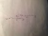
Word visual, because I do not see a way to attach a picture
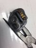
relay pin out
1: coil
2: coil ground
3: wiper
4: NO contact

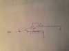
a Wire from the switch to term #1, piggy backed to term #3
b term #2 goes to ground
c term #4 goes out to the brake lights

What say you, thanks in advance

Greg
 

Bluejets

Oct 5, 2014
6,942
Joined
Oct 5, 2014
Messages
6,942
2 x 21w bulbs approx 2 amp. doubt that will cook the brake switch.
I have a 40 year old Celica that is still going strong, no brake switch replacement.
Apart from that, cannot follow the logic you present with the relays.
 

pepi

Sep 20, 2017
30
Joined
Sep 20, 2017
Messages
30
Standard 12 vdc auto supply. The bulbs are 1157 and there are 4.

1157-jpg.36270


imho I believe it is just a cheap switch, rated @ 40 amps. Looking at the condition of the wiper and contacts has me believing 40 amps is hype.
So I'm going to move the load of the lamps to a relay, and have the switch trigger the coil, bottom drawing #2.
img_2114-jpg.36272


@ bluejets, not understanding your not understanding

The number 1-4 are the relay terminals.

However a thanks to you bluejets. Drawing the circuit, first picture.. I found my own answered to the question seen in picture two..

first
ref-jpg.36273

second
correction-jpg.36274

One again prof that a picture is worth a thousand words LOL

Greg
 

Attachments

  • 1157.jpg
    1157.jpg
    26.3 KB · Views: 137
  • IMG_2114.jpg
    IMG_2114.jpg
    90.2 KB · Views: 160
  • ref.jpg
    ref.jpg
    76.4 KB · Views: 150
  • correction.jpg
    correction.jpg
    90 KB · Views: 143
Last edited:

Tha fios agaibh

Aug 11, 2014
2,252
Joined
Aug 11, 2014
Messages
2,252
Your load should only be 8.5amps.
If you were really overloading the circuit you'd be blowing fuses.

Perhaps there is something wrong with the type of switch or the install?

Another work around could be to use low current leds instead of ge1157 lamps.
 

pepi

Sep 20, 2017
30
Joined
Sep 20, 2017
Messages
30
I agree it's the switch that is the problem, seems to be arcing as it cycles. Using it to only trigger the relay coil I believe will solve the problem.

I must nix the leds thought, they are to modern to be run on a 32 pick up, same goes for the 34. :)

Thank you for your time and recommendations.

Regards,
Greg
 

duke37

Jan 9, 2011
5,364
Joined
Jan 9, 2011
Messages
5,364
If you use a relay, then add a flyback diode across the relay coil to reduce switch sparking when switched off.
Most motor equipment is crude and relies on fat cheap contacts.
 

Kiwi

Jan 28, 2013
472
Joined
Jan 28, 2013
Messages
472
Not unusual for four 21W bulbs to be a bit hard on the switch, causing it to fail prematurely.

Second diagram shows the correct way to connect the relay, but the four bulbs are in parallel, not series as drawn.
As duke advised. a diode should be connected across the relay coil to protect the switch contacts.
A 1N4007 diode would be suitable.
 

pepi

Sep 20, 2017
30
Joined
Sep 20, 2017
Messages
30
Drawing #1 is picturing the worded description found in the first post. After looking it over, I saw my error and answered my own question. Thus to clarity I posted the second picture as the proper method for the install.

The string of bulbs just there, not real world, drove the truck yesterday.

Thanks,
Greg
 
Top