Maker Pro
Maker Pro

Resistance of different points of a circuit

SanMiguel

Sep 22, 2015
4
Joined
Sep 22, 2015
Messages
4
Hi there. I have been asked a question. I have to work out the resistance at points A, B, C and D. It is a very basic circuit which consists of 4 resistors of different values.

The resistors are as follows.
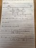
R1- 10k ohms
R2- 2.2k ohms
R3- 10k ohms
R4- 22k ohms

Please find attached a circiit diagram and my calculations.

Please could you let me know if I am right? Thanks a lot.
 

Attachments

  • image.jpg
    image.jpg
    199.2 KB · Views: 112

Laplace

Apr 4, 2010
1,252
Joined
Apr 4, 2010
Messages
1,252
There is some conceptual difficulty with the terminology "resistance at a point" because resistance is measured between two points. From your calculations it is not immediately clear what that other point is.
 

hevans1944

Hop - AC8NS
Jun 21, 2012
4,887
Joined
Jun 21, 2012
Messages
4,887
... I have to work out the resistance at points A, B, C and D.
There is no such thing as resistance at a point. Resistance, like voltage or potential, is always measured between two points. A = 100 kΩ is meaningless.

If your point A were on the other side of R1, you could consider the resistance from A to B with R3 and R4 removed from the circuit to be B = 12.2 kΩ; or from A to C with R2 and R3 in parallel and R4 removed from the circuit to be C = 11803 Ω; or from A to D with R2, R3, and R4 in parallel to be D = 11667 Ω. Then, all three equations are correct under these conditions.

Avoid the use of "X" as a schematic symbol to indicate broken connections. If you do decide to do this, describe precisely under what conditions the connection is broken and why it is broken.

Oh, and welcome to Electronics Point!
 

SanMiguel

Sep 22, 2015
4
Joined
Sep 22, 2015
Messages
4
Yes, sorry. The first point is just before R1 (to the left of this resistor on the circuit shown).
The second point is A, B, C and D.

Thanks.
 

SanMiguel

Sep 22, 2015
4
Joined
Sep 22, 2015
Messages
4
There is no such thing as resistance at a point. Resistance, like voltage or potential, is always measured between two points. A = 100 kΩ is meaningless.

If your point A were on the other side of R1, you could consider the resistance from A to B with R3 and R4 removed from the circuit to be B = 12.2 kΩ; or from A to C with R2 and R3 in parallel and R4 removed from the circuit to be C = 11803 Ω; or from A to D with R2, R3, and R4 in parallel to be D = 11667 Ω. Then, all three equations are correct under these conditions.

Avoid the use of "X" as a schematic symbol to indicate broken connections. If you do decide to do this, describe precisely under what conditions the connection is broken and why it is broken.

Oh, and welcome to Electronics Point!

Thanks For the help.

To clarify the first 'point' is before the resistor R1, to the left. So let call this point 'Y' so it will be between points:

Y and A
Y and B
Y and C
Y and D

Hope that's clearer.
 

Old Steve

Jul 23, 2015
734
Joined
Jul 23, 2015
Messages
734
Is R1 10K or 100K? 10K, I suppose, so alter answer A from 100K to 10K.

Answers B, C & D are correct.

I'm assuming that the circuit is cut at B to measure B and cut at C to measure C, so that the resistors to the right of these points are not in circuit.
 
Last edited:

davenn

Moderator
Sep 5, 2009
14,267
Joined
Sep 5, 2009
Messages
14,267
I'm assuming that the circuit is cut at B to measure B and cut at C to measure C, so that the resistors to the right of these points are not in circuit.

I suspect that isn't the case as that wasn't mentioned
rather the circuit is resistance values are measured as the circuit is seen
and therefore his cal's are incorrect as they don't take into account the series resistor value

The resistance value at B, C, D are going to be the same as it is a common node

equiv circuit

resistors.GIF


Dave
 
Last edited:

Old Steve

Jul 23, 2015
734
Joined
Jul 23, 2015
Messages
734
I suspect that isn't the case as that wasn't mentions
rather the circuit is resistance values are measured as the circuit is seen
and thesefore his cal's are incorrect as they don't take into account the series resistor value
The resistance value at B, C, D are going to be the same as it is a common node
equiv circuit
View attachment 22153


Dave
We'll have to wait until he answers, I guess.
It seemed to me to be a silly question if it wasn't cut at B and C, but could have been a trick question.
(He was logged on here for quite some time after my reply, but didn't respond.)

And "D" is still correct in his calculations. "A" would have been too, if he'd altered the 100K to 10K as he did elsewhere on the page.

Edit: So the result is 1/4 - a fail.
(If you're correct.) And 2/4 for me. Another fail. :oops:
 
Last edited:

Old Steve

Jul 23, 2015
734
Joined
Jul 23, 2015
Messages
734
Actually, I can remember some 'trick' questions like this when I was studying basic electronics too.
More of a 'clear thinking' exercise than anything else.
(At least I did qualify my answer here by mentioning cutting at B and C - you can't do that in an exam. :D )
 

hevans1944

Hop - AC8NS
Jun 21, 2012
4,887
Joined
Jun 21, 2012
Messages
4,887
I guess the important thing here is knowing how to calculate the values for series and parallel resistor configurations. You need to remember that series resistances add and that parallel resistances, expressed as conductance G = 1/R, also add. Convert all parallel resistor values to conductance and add to find the equivalent conductance, then take the reciprocal of that conductance to convert back to equivalent resistance. Add this to whatever resistances are in series.

Now confuse things by trying to calculate the resistance between any two terminals of a five-resistor bridge circuit with all resistors unequal to each other. Hint: assume a voltage is applied to the two arbitrary terminals and use Ohm's Law and Kirchoff's laws to find the current and voltage distributions across each resistor.
 

Old Steve

Jul 23, 2015
734
Joined
Jul 23, 2015
Messages
734
I guess the important thing here is knowing how to calculate the values for series and parallel resistor configurations.
From that point of view, he's on the right track. A lot of beginners have trouble with series-parallel circuits.
 

SanMiguel

Sep 22, 2015
4
Joined
Sep 22, 2015
Messages
4
Hi everyone. Thanks a lot for all your replies. I've been a bit overwhelmed as I didn't expect so much help. Apologies for only just replying. I posted this from my phone and forgot to logout (hence being logged in for so long).

Yes for A I certainly did mean 10kohms. Just goes to show you should always double check answers (or perhaps I was testing you guys haha).

This is the reason I posted this question, as I was unsure of the correct way of doing it. Whether it was my way or davenn's way.

I think davenn's way does make much more sense to me though.

The way this question was laid out and 'asked' when I originally answered it was exactly how it was above. I'm not even sure Y was present. Could've been but in not sure.

But it certainly was a bit of a 'trick' question.

Thanks again for your replies.
 

davenn

Moderator
Sep 5, 2009
14,267
Joined
Sep 5, 2009
Messages
14,267
This is the reason I posted this question, as I was unsure of the correct way of doing it. Whether it was my way or davenn's way.

I think davenn's way does make much more sense to me though.

The way this question was laid out and 'asked' when I originally answered it was exactly how it was above. I'm not even sure Y was present. Could've been but in not sure.

But it certainly was a bit of a 'trick' question.

Its always a good thing, where possible, to rearrange the components into a more recognisable layout.
The problem then becomes much clearer and easier to understand :)

That first really important step was to recognise that A was one common node and B, C, D was the other common node for the parallel resistors.
Rearranging the resistors makes that visually clearer


you are doing great, keep up your activities and look forward to hearing more from you on the forum :)


Dave
 
Top