Maker Pro
Maker Pro

Replacing solar module with DC output

flamer

Oct 22, 2012
37
Joined
Oct 22, 2012
Messages
37
Hi guys, I have 6 sets of solar lights in my outdoor area (aliexpress), each has its own solar panel/battery unit, for two years they all worked great now only one works. Rather than replace all the batteries I thought I would be better off wiring them into my shed where I have AC mains and use a DC wall plug.

The battery in each are the same, a single 1.2v 800mah nimh.

Is it true I will actually need a 3v output to drive these? Also will that risk burning them out since they are used to 3v alternating? I will also lose the different modes - flashing/pulsing etc and the auto on at dusk, I can use a timer for that though.

Anything else I need to consider?
 

Bluejets

Oct 5, 2014
6,981
Joined
Oct 5, 2014
Messages
6,981
Is it true I will actually need a 3v output to drive these? Also will that risk burning them out since they are used to 3v alternating? I will also lose the different modes - flashing/pulsing etc and the auto on at dusk, I can use a timer for that though.
If it's supplied with 1.2v now.....3v will cook it.
No idea what the waffle about 3v alternating is all about.
Modes are set in the unit , on at dusk is a simple ldr switcher , or may simply monitor solar panel voltage and switch from there, so it depends how you connect to the new supply.
Draw a circuit of the device/devices, post here and some might be able to add a useful comment.
 

flamer

Oct 22, 2012
37
Joined
Oct 22, 2012
Messages
37
ezgif-5-7da30df9dd.gif
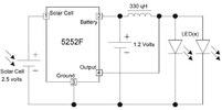
This is the schematic, the waffle about 3v alternating is, as we know 1.2 volt is not enough to light an led, so this circuit boosts it to 3v and rapidly pulses the led off and on faster than the eye can see.

The plan was to connect a 3v supply directly to the leds bypassing the circuit completely, my second option is to attach a 1.2v supply to the battery terminals of the circuit so I can keep the auto on off function and the flashing modes, but then I need to prevent the panel sending a charging voltage down to the supply during the day and also not sure this one circuit will like 6 sets of lights hanging off it
 

Harald Kapp

Moderator
Moderator
Nov 17, 2011
13,758
Joined
Nov 17, 2011
Messages
13,758
this circuit boosts it to 3v and rapidly pulses the led off and on
Not quite. The chip controls the current, not the voltage. The datasheet doesn't give good information, but the gist is that the power to the LED is controlled by selecting the right inductor.

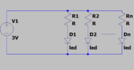
Anyway: you can't drive LEDs with a voltage source alone. LEDs are current driven and require either a current source or at least a current limiting resistor. See e.g. our resource on driving LEDs. In your case a series resistor (one for each LED) is probably the most simple solution:
1698050681585.png
The resource I linked shows how to calculate the value R for the resistor depending on the required current and the voltage drop of the LED.
You can also use e.g. a cheap 5 V USB wall wart to supply this circuit instead of a potentially not so easy to acquire 3 V power source. All you need to do is change the value for R to adapt the circuit to the 5 V source.
 

flamer

Oct 22, 2012
37
Joined
Oct 22, 2012
Messages
37
Not quite. The chip controls the current, not the voltage. The datasheet doesn't give good information, but the gist is that the power to the LED is controlled by selecting the right inductor.

Anyway: you can't drive LEDs with a voltage source alone. LEDs are current driven and require either a current source or at least a current limiting resistor. See e.g. our resource on driving LEDs. In your case a series resistor (one for each LED) is probably the most simple solution:
View attachment 61164
The resource I linked shows how to calculate the value R for the resistor depending on the required current and the voltage drop of the LED.
You can also use e.g. a cheap 5 V USB wall wart to supply this circuit instead of a potentially not so easy to acquire 3 V power source. All you need to do is change the value for R to adapt the circuit to the 5 V source.

thank you very much, that link has answered almost everything!
 
Top