Maker Pro
Maker Pro

Outdoor string lights keep faulting

flamer

Oct 22, 2012
37
Joined
Oct 22, 2012
Messages
37
Hi all, I posted a while ago about converting my solar lights to mains current, well now that's done I have been having quite a few problems.

Ill try to keep it short - So I wired 7 sets of string lights together (~1000 total leds) in parallel and connected them to a 3v watch battery, all worked well, I needed to do some re-jigging of the led's strings themselves (they are attached to a fence and drooping a bit) after I completed that and connected them to their 3v power supply they no longer worked, I put the ohm meter across the + and - leads and got a reading of about 8ohm, where I should have got open line. So I disconnected all 7, found two sets where showing a short (I suspected I have crossed a wire when re-fixing them), I couldn't for the life of me find the issue on either set and ended up chucking those out and replacing with another two sets , these two new ones were not solar they were wired and both came with a usb power source but they were an identical product to the existing ones.

I decide the included usb power may be better than my 3v buck converter so I wired that usb supply in, and they all worked great. The following night.. no lights. I cut the wires and sure enough I have a short again, I find a bit of cable wedge behind a fence post on one of the led sets as I pull it out it snaps, I measure resistance in both directions and its open, well fantastic, resoldered it and I think I've fixed it. the lights run perfectly for 2 nights on the usb power (its plugged into a powerboard with usb plug upto 2.1 amp supplied)

Well surprise surprise, now guess what, night 3 no lights again, I cut the line close to the power supply, and I'm showing 8ohms of resistance again so another short circuit. I isolated the previously bad set again, that is not showing a short, but I see the short on the other side of the cut where the remaining 6 sets are.

Needless to say I am going a bit insane here, I can understand if I was overvolting/currenting them I would have problems, but its almost the opposite I wasn't sure if the single usb can handle the load but but when they worked they looked good same brightness as they were on solar.

One thing to add is, these led strings have been in place for 2 years, on solar they were running fine every night till the batteries went flat.

Is it possible one of these tiny leds has burned out and created a short? is there any practical way to find that? As it would be very easy to just pull the led off the strand, as once I do find the set with the short ill probably need to bin it and replace it (this might become a daily occurrence). The strings themselves have not been touched between the time they worked and the stime they stopped working.

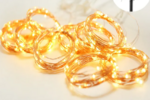
For info the product are resin dipped led curtain lights -
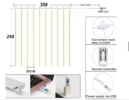
1703826562725.png
 

Delta Prime

Jul 29, 2020
2,035
Joined
Jul 29, 2020
Messages
2,035
One thing to add is, these led strings have been in place for 2 years,

Sounds to me like
photo-degradation.
Exposure to ultraviolet (UV) radiation can cause the significant degradation of many materials.
UV radiation causes photo-oxidative degradation which results in breaking of the polymer chains, reduces the molecular weight, causing deterioration of mechanical properties and leading to useless materials.
I put the ohm meter across the + and - leads and got a reading of about 8ohm,
You have eight ohm test leads? I caramba!
Keep them out in the sun that'll take care of them. They'll be down to zero ohms in about 2 years.
 

flamer

Oct 22, 2012
37
Joined
Oct 22, 2012
Messages
37
Sounds to me like
photo-degradation.
Exposure to ultraviolet (UV) radiation can cause the significant degradation of many materials.
UV radiation causes photo-oxidative degradation which results in breaking of the polymer chains, reduces the molecular weight, causing deterioration of mechanical properties and leading to useless materials.

You have eight ohm test leads? I caramba!
Keep them out in the sun that'll take care of them. They'll be down to zero ohms in about 2 years.

Thanks for the reply, sorry no I meant I connected the multimeter probes to the wires feeding the lights and got 8 ohm resistance showing. If I touch the probes together I get 0.00.

The only new material I have introduced into this setup is about 3 meters of 2 core wire from the power source to the lights, the lights themselves are outdoor lights (IP66) and have been installed there for years


Is it possible by chaining so many lights together they are drawing too much current and has fused one ore more LEDs causing the whole circuit to stop working?
 

Delta Prime

Jul 29, 2020
2,035
Joined
Jul 29, 2020
Messages
2,035
Is it possible one of these tiny leds has burned out and created a short?
Yes they can fail short circuit and they can fail open circuit. Before they fail they can be intermittent.
is there any practical way to find that?
Yes if your multimeter has a diode test setting use that, when you forward bias the LED it should light up faintly and if you reverse bias the LED nothing should happen but if it does light up then that's a problem. There's no voltage standard for diode tests on multimeters so you must be careful because different manufacturers of multimeters use a higher voltage than others and you can damage or destroy the LED itself while you're testing it.
Is it possible by chaining so many lights together they are drawing too much current and has fused one ore more LEDs causing the whole circuit to stop working?
That is within the realm of possibilities.
For info the product are resin dipped led curtain lights
Nice photo name of the manufacturer please. Or link to where you purchased your item.
As it would be very easy to just pull the led off the strand, as once I do find the set with the short ill probably need to bin it and replace it (this might become a daily occurrence).
I would assemble one set apply power and take measurements voltage current. Of the entire string and of One or two LED's see what the voltage is across it. Draw a diagram of a single set and annotated your drawing with your measurements. Now you know exactly what is required when you modify a single set. Then if you'd like, provide us that information and we can double check for any practical ideas of your designs (modifications)if you wish to add or subtract to your fairy light curtain.
Happy New Year.
 

flamer

Oct 22, 2012
37
Joined
Oct 22, 2012
Messages
37
Yes they can fail short circuit and they can fail open circuit. Before they fail they can be intermittent.

Yes if your multimeter has a diode test setting use that, when you forward bias the LED it should light up faintly and if you reverse bias the LED nothing should happen but if it does light up then that's a problem. There's no voltage standard for diode tests on multimeters so you must be careful because different manufacturers of multimeters use a higher voltage than others and you can damage or destroy the LED itself while you're testing it.

That is within the realm of possibilities.

Nice photo name of the manufacturer please. Or link to where you purchased your item.

I would assemble one set apply power and take measurements voltage current. Of the entire string and of One or two LED's see what the voltage is across it. Draw a diagram of a single set and annotated your drawing with your measurements. Now you know exactly what is required when you modify a single set. Then if you'd like, provide us that information and we can double check for any practical ideas of your designs (modifications)if you wish to add or subtract to your fairy light curtain.
Happy New Year.

thanks for your inputs, here are some details

- using my 3 volt battery on one set of lights (isolated from the others) I can get them to light up and measure 15 milliamp of current draw. (My MM does have a diode function but it only beeps it doesn't light up even a single LED)

- the leds are soldered directly onto copper then coated with an insulant, so the only testing method is right at the end of the wires -
1703908990098.png

- I can confirm the led's all light (same brightness) regardless of polarity. I don't know what that means, I have confirmed with the same power source a single test led only lights in the correct polarity (just to verify my own test method).

This is the product:

I would be interested to know, if I do go back to my buck convertor supply what size resistor should I use? I run it at 3v output, and the draw would be 7x 15ma?

thanks and happy new years!
 

Delta Prime

Jul 29, 2020
2,035
Joined
Jul 29, 2020
Messages
2,035
I would be interested to know, if I do go back to my buck convertor supply what size resistor should I use? I run it at 3v output, and the draw would be 7x 15ma?
I would be happy to tell you exactly what will happen if you went back to your buck converter supply...
Make,model, link, of your buck converter please.
You see where this is going...
I cannot give you proper advice without the necessary information.
I will not critique your test method. Perhaps I can supplement your (MO)Motive Operandi. Before the new year.
Until then I will keep father time at Bay. Thank you sir.
 

Harald Kapp

Moderator
Moderator
Nov 17, 2011
13,758
Joined
Nov 17, 2011
Messages
13,758
This is the product:
Link is inop.

I'm not sure what you are actually measuring, but your explanation doesn't make sense to me. You state:
I put the ohm meter across the + and - leads and got a reading of about 8ohm, where I should have got open line.
Why would you expect an open line? Depending on the typ of multimeter and the range you use, you may measure the resistance of the parallel circuit of all the LEDs, not an open circuit.

Next you state:
disconnected all 7, found two sets where showing a short
That would give a reading of 0 Ω, not 8 Ω.

I decide the included usb power may be better than my 3v buck converter
Not necessarily better but the included power supply may provide an essential property that the buck converter is missing: Constant current!
See, LEDs cannot be operated on a pure voltage source. They need to be supplied by a power source that limits the current through the LEDs.
Since there are no obvious current limiting elements in the LED strings as I assume from this statement:
the leds are soldered directly onto copper then coated with an insulant
The current limiting is most likely (if not obviously) done within the original USB power source.
Without current limiting the LEDs will draw too much current and fail. You may read up more detail in our resource section.

The reason why the LEDs seem to work from a 3 V coin cell (although I agree with @Bluejets that a single 3 V coin cell will light up hundreds of LEDs) is that these coin cells (I assume you used something like a CR2032 or similar) can deliver only a limited current. In a way (although technically not very correct) they have a built-in current limiter because the cells chemistry can deliver only a limited amount of power at a time.
Your buck converter otoh may deliver way too much power. If you want to stick to your buck converter, you have two simple possibilities:
  1. Use current limiting if the buck converter has this option.
  2. If not, use a series resistor from the output of the converter to the LED string to limit the current (see also the resource I linked to find out which resistor you would need).
 
Top