Maker Pro
Maker Pro

LED Aquarium light fixture

JBsHut

Aug 21, 2023
7
Joined
Aug 21, 2023
Messages
7
Hello All, please forgive me if this is not the right location for this thread.
I've been owning an aquarium light fixture for the past 8 years, and it has been working very well (72 pcs of SMD 5730: 62 white, four blue, four red and two green).
Lately, after about five minutes it turns off. None of the LEDs are burnt, but it takes about 15 minutes or so until I can reconnect it to the power supply and turn it for another five minutes. I assume that it has to do with the driver, which is connected to a whole bunch of buttons I've never used, as I power it and control it with a different unit (8 hours of light each day, only on\off).
So I've decided I'd like to bypass the driver. I know that the driver is the one in charge of the dimming capabilities, color adjustments, and protection mechanisms to prevent overcurrent, overvoltage, and other electrical issues that might arise, but I've had my experience and am willing to take the risk of burning through these LEDs (the alternative as I see it is tossing them and replacing them with a bunch of LED strips using the metallic fixture for the better heat exchanging).
So I tore through the fixture and found out that I have three outlets from the driver, marked + (quite obvious), W and B (less obvious).
Any recommendations as to what those mean?
Any tips in general? Thanks!
 

Attachments

  • 3b079c9d-04a3-452c-934a-0407b77264f1.jpg
    3b079c9d-04a3-452c-934a-0407b77264f1.jpg
    119.8 KB · Views: 10
  • Screenshot 2023-08-21 175702.png
    Screenshot 2023-08-21 175702.png
    1.1 MB · Views: 9

JBsHut

Aug 21, 2023
7
Joined
Aug 21, 2023
Messages
7
One cannt bypass the driver.
Okay. Would you say that any off-the-shelf driver you know of could act as a replacement to the below? I'm having a hard time understanding what's the difference between the LED W and the B, I would have assumed 'White' and 'Blue' but we also have the green and red, and we'd be missing the ground.
I can easily remove the drive and add an external one instead. There's a converter up the line, so the inlet to the driver 36W 1.5A. I assume I'd have to toss the converter, since most of the drivers I see online include the converter.
 
Last edited:

Harald Kapp

Moderator
Moderator
Nov 17, 2011
13,758
Joined
Nov 17, 2011
Messages
13,758
It seems there are two types of LED on the pcb, marked B_1 and W_1:
1692681716801.png1692681724894.png
These are likely to be controlled by the B and W lines on the connector.
There is also a bunch of resistors on the LED pcb, indicating that the driver is not a constant current LED driver but a voltage source. The resistors will limit the current through the LEDs when a voltage is applied.
we'd be missing the ground.
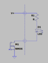
Actuall: no. This kind of LED lamp is typically driven with a switched ground like so:
1692682018208.png
The reason being that N-MOSFETs are more effective in terms of price/power than P-MOSFETs. Therefore the LEDs are permanently connected to "+" and the ground side is switched. Intensity is then controlled by varying the duty cyycle (on/off) which is called pwm.

To replace the driver you need to know the output voltage of the existing driver (measured between "+" <> "W" or "+" <> "B").

From thge timing behavior that you describe it looks like a thermal effect: A componnet starting to overheat, then the driver turns off until the component has cooled down. The imho most likely culprit would be the driver MOSFETs. Can you post an enlarged and clear picture of this section?

1692682524591.png

We may be able to determine the type of MOSFET and suggest which componnets to replace.
 

JBsHut

Aug 21, 2023
7
Joined
Aug 21, 2023
Messages
7
Thank you Harald for the thorough response, I did indeed not notice the numbering on the LEDs themselves, and the "lack" of grounding does make sense now.
I did fear that a thermal unit has failed, but I saw no reason for overheating in the system, since it has not changed in the last few years, only if something went wrong - and so I thought that changing the whole driver would solve that.
Please see attached the close ups, if any more information is required please let me know.
In the meantime, I will be measuring the voltage between the "+" <> "W" or "+" <> "B" as suggested.
Thanks again
 

Attachments

  • WhatsApp Image 2023-08-22 at 10.35.37.jpeg
    WhatsApp Image 2023-08-22 at 10.35.37.jpeg
    358 KB · Views: 10
  • WhatsApp Image 2023-08-22 at 10.35.28.jpeg
    WhatsApp Image 2023-08-22 at 10.35.28.jpeg
    387.1 KB · Views: 10
  • WhatsApp Image 2023-08-22 at 10.35.04.jpeg
    WhatsApp Image 2023-08-22 at 10.35.04.jpeg
    280.2 KB · Views: 9

Harald Kapp

Moderator
Moderator
Nov 17, 2011
13,758
Joined
Nov 17, 2011
Messages
13,758
Looks like these 4812 ICs are AO4812 power MOSFETs from Alpha and Omega semiconductor.
There are 2 MOSFETs in one package:
1692765744362.png
These are the drier MOSFETs for the LEDs and should not get hot, warm to the hand at best. If these get hot, there is to much power dissipation which may cause the driver to turn off.
I don't see where you could buy one of these MOSFETS, but a suitable replacement seems to be the ZXMN3G32DN8, available e.g. here.
 

JBsHut

Aug 21, 2023
7
Joined
Aug 21, 2023
Messages
7
Hi Harald, thanks again.

I have looked up the ZXMN3G32DN8 & AO4812 locally, they both are available but seem to be a little more expensive (because of the minimum quantity required for order) than purchasing a new driver online that would be installed externally to the light fixture, so I'm looking into that solution parallely, assuming that some other electronic elements on the PCB might be ending their lives soon. I have tested the voltage between the "+" <> "W" or "+" <> "B" and the both of them are ~19V, I assume it's 20V because my measuring device is an old MICRONTA Range Doubler. Have you any suggestion for a driver of that sort?
 

JBsHut

Aug 21, 2023
7
Joined
Aug 21, 2023
Messages
7
Thanks, I still very much appreciate the help.
I'm willing to toss the old power supply as well, I know that today companies produce them combined every now and again.
 

73's de Edd

Aug 21, 2015
3,634
Joined
Aug 21, 2015
Messages
3,634

Sir JBsHut . . . . . . .​

Lately, after about five minutes it turns off. None of the LEDs are burnt, but it takes about 15 minutes or so until I can reconnect it to the power supply and turn it for another five minutes. (For then, yet another like expected run time.)
I have several questions needed in my making of a fully and validly structured analysis . . . but initially . . . consider that this might be attributed to a time of use,developed fallacy of the units power supply.
If it is being of switch mode design, they are CERTAINLY related to more timely failure than old school linear design supplys.
A hint may be on the nameplate and identification of that power supply power housing. Linear types are usually specific in 50 or 60 cycle use
along with a quantified 120 VAC OR 220 VAC line power input, while the switch mode can accept a broad spectrum 100-240 AC or DC line power input . . . .which is yours ?

After looking at the driver board
I would be more suspect of that units power supply with 8 years of daily use and the accumulated hours that it has run.
An initial exploratory test would be to take DC metering in hand and monitor the input into the board with the brown and blue power input lines and confirm that same voltage that you initially read before. Then stand by for the 5 min cut off threshold time to approach, and confirm if that voltage level remains after the failure. If the voltage drops off or goes down, that's suggesting a thermal cut off of the power supply after warmup.
If you are using a timer with this system, its logical that it comes on at the desired light sequencing at each power up. Are the three leds on the circuit board proper, mimicking strip lighting sequencing ?
I can see the boards very end and the inputs of controls to the ports of the STC 12C5606ad uProcessor . . . . . but what does the BUZ KSS-74G15 combination buzzer / momentary contact push button switch on top do ?
( I can see its buzzer beeping on confirmation of any of the other control switches presses. )
I am seeing input power being routed to the right to the U4 3 terminal regulator to supply its 3/or/5 v to the uP. With the use of hi density mmic
high density block ceramic capacitors as the C6 input and C7 output filters . . . . . vice conventional electrolytic units . . . . there just aren't being any "troublesome " components incorporated on that driver board.
If you find power intact AND remaining after LED lighting loss . . . . lets investigate them next and also the Dual power switching FETS that have their gates activated by the 24k resistors being fed in from uP ports.

73's de Edd . . . . .


Somebody just told me that . . . . . and I absolutely heard it with my own two ears . . . . that fifteen plus fifteen equals thirty, and sixteen plus sixteen equals thirty too.
I have just GOT to check that out, more fully!


.
 
Last edited:

Martaine2005

May 12, 2015
4,956
Joined
May 12, 2015
Messages
4,956
Somebody just told me that . . . . . and I absolutely heard it with my own ears . . . . fifteen plus fifteen equals thirty, and sixteen plus sixteen equals thirty too.
I have just got to check that out, more fully!
Hahaha, I had to read that free times before my brain saw the error:):)
 

JBsHut

Aug 21, 2023
7
Joined
Aug 21, 2023
Messages
7

Sir JBsHut . . . . . . .​

Lately, after about five minutes it turns off. None of the LEDs are burnt, but it takes about 15 minutes or so until I can reconnect it to the power supply and turn it for another five minutes. (For then, yet another like expected run time.)
I have several questions needed in my making of a fully and validly structured analysis . . . but initially . . . consider that this might be attributed to a time of use,developed fallacy of the units power supply.
If it is being of switch mode design, they are CERTAINLY related to more timely failure than old school linear design supplys.
A hint may be on the nameplate and identification of that power supply power housing. Linear types are usually specific in 50 or 60 cycle use
along with a quantified 120 VAC OR 220 VAC line power input, while the switch mode can accept a broad spectrum 100-240 AC or DC line power input . . . .which is yours ? 225V 50Hz AC socket, and the power supply is 24VDC 1.5A

After looking at the driver board
I would be more suspect of that units power supply with 8 years of daily use and the accumulated hours that it has run.
An initial exploratory test would be to take DC metering in hand and monitor the input into the board with the brown and blue power input lines and confirm that same voltage that you initially read before. Then stand by for the 5 min cut off threshold time to approach, and confirm if that voltage level remains after the failure. If the voltage drops off or goes down, that's suggesting a thermal cut off of the power supply after warmup. Wonderful idea, I have however removed the driver completely as I wrote below. It would be quite an interesting test to run, although I have changed the power supply to a lower capacity one I had at hand, and it did not turn off after 5 minutes - although it might have to do with the lower capacity.
If you are using a timer with this system, its logical that it comes on at the desired light sequencing at each power up. Are the three leds on the circuit board proper, mimicking strip lighting sequencing ? Nope, they're for controlling the different light modes (which I've never used) - Thunderstorm (useless aquarium plant growth-wise), sunrise\sunset (also useless) and regular mode - which I constantly used.
I can see the boards very end and the inputs of controls to the ports of the STC 12C5606ad uProcessor . . . . . but what does the BUZ KSS-74G15 combination buzzer / momentary contact push button switch on top do ? The buzzing is to indicate the switching between the different modes, and to indicate the internal on\off 8h countdown.
( I can see its buzzer beeping on confirmation of any of the other control switches presses. )
I am seeing input power being routed to the right to the U4 3 terminal regulator to supply its 3/or/5 v to the uP. With the use of hi density mmic
high density block ceramic capacitors as the C6 input and C7 output filters . . . . . vice conventional electrolytic units . . . . there just aren't being any "troublesome " components incorporated on that driver board.
If you find power intact AND remaining after LED lighting loss . . . . lets investigate them next and also the Dual power switching FETS that have their gates activated by the 24k resistors being fed in from uP ports.

73's de Edd . . . . .


Somebody just told me that . . . . . and I absolutely heard it with my own two ears . . . . that fifteen plus fifteen equals thirty, and sixteen plus sixteen equals thirty too.
I have just GOT to check that out, more fully!


.
Hi 73's de Edd, thanks for the reply!
Please see above in blue as for my response. In the meantime, I have gotten this and connected both the B and the + to the V+, and the W to the V-. I've tested it by keeping it going for about 30 minutes before having to shut it down b/c I had to leave the house. I'll be controlling it externally as for the on\off. I have not played with any of the other options ever anyway, so it seems to be a legitimate solution in the meantime.
 

73's de Edd

Aug 21, 2015
3,634
Joined
Aug 21, 2015
Messages
3,634

Sir JBsHut . . . . . . .​

I've tested it by keeping it going for about 30 minutes before having to shut it down b/c I had to leave the house.
So, effectively, you DID replace the old power supply and it certainly is now FAR exceeding the initial power supply's state of possible run time..
It would be VERY informative to now go back and hook up the original supply and, at a cold start, have multi meter in its 10 amp or 2A current range . Have the leads in series with the + input wire and monitor the current being pulled.
You then might even wait out the typical 5 min to see what the meter is showing at the cut off point of LED illumination.
THEN reinstall your new supply and confirm if its current pull is meeting the requirement that was being supplied with the original power pack.
Then I guess its time for another 8+ yrs of service . . . . unless this new supply turns out to be of less durability than the old one.
($2.62 . . . . . . two dollah sixty too cents . . . . . . . . . BABYCAKES !) . . . . . . such a deal already !)

Thaaaaaaaaassit . . . . . .

73's de Edd . . . . .

WOW ! . . . . . . I do think that I just spotted an albino dalmatian.


.
 
Last edited:

JBsHut

Aug 21, 2023
7
Joined
Aug 21, 2023
Messages
7

Sir JBsHut . . . . . . .​

I've tested it by keeping it going for about 30 minutes before having to shut it down b/c I had to leave the house.
So, effectively, you DID replace the old power supply and it certainly is now FAR exceeding the initial power supply's state of possible run time..
It would be VERY informative to now go back and hook up the original supply and, at a cold start, have multi meter in its 10 amp or 2A current range . Have the leads in series with the + input wire and monitor the current being pulled.
You then might even wait out the typical 5 min to see what the meter is showing at the cut off point of LED illumination.
THEN reinstall your new supply and confirm if its current pull is meeting the requirement that was being supplied with the original power pack.
Then I guess its time for another 8+ yrs of service . . . . unless this new supply turns out to be of less durability than the old one.
($2.62 . . . . . . two dollah sixty too cents . . . . . . . . . BABYCAKES !) . . . . . . such a deal already !)

Thaaaaaaaaassit . . . . . .

73's de Edd . . . . .

WOW ! . . . . . . I do think that I just spotted an albino dalmatian.


.
Thanks again for the thorough response. Absolutely agree, and would be done. I'll report the results here :cool:
 
Top