Maker Pro
Maker Pro

Wiring on Pedal Assist Bike

joseph Jerome E. Sanchez

Sep 17, 2018
13
Joined
Sep 17, 2018
Messages
13
Hello good evening everyone,


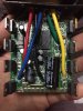
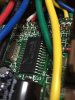
I`m hoping to find help from this thread. My son`s pedal assist bike has stopped working and upon inspection, we found 3 wires unsoldered from the crank and when we open it, there`s no way for me to figure out how to solder. This bike is very important to him since he uses it to go from our home to his school. Please note I don`t have knowledge in electronics just know how to solder. I don`t even have a tester right now but willing to buy one but doesn`t know how to use it (but willing to learn just don`t know where to start). My son and I are hoping it`s an easy fix so we appreciate any help you guys can give us. Attached here are the pictures of the said board.


Thank you so much.


Your`s truly,
Joseph JeromeIMG_6796.JPG IMG_6797.JPG IMG_6798.jpg IMG_6799.JPG IMG_6800.JPG IMG_6801.JPG IMG_6802.JPG IMG_6802.JPG
 

(*steve*)

¡sǝpodᴉʇuɐ ǝɥʇ ɹɐǝɥd
Moderator
Jan 21, 2010
25,510
Joined
Jan 21, 2010
Messages
25,510
Well... It's will be an easy fix. Just solder the wires back where they came from.

The major problem is finding out which wires go where.

I would start by looking very carefully at each joint, looking for a small bit of insulation, or some evidence about which wire connected there (maybe there is a short and 2 long strands at the end of one wire, and there is a slightly longer strand on the matching solder joint.

If you know anyone who has one of these bikes you could look at an intact board.
 

Bluejets

Oct 5, 2014
6,927
Joined
Oct 5, 2014
Messages
6,927
Photos 1,2,3,and 4 and possibly 6 are good, the rest are not much use.
Need to see internal details of the unit it plugs in to ...bit of a description about what it does would help.
Chips are op amp and flip-flop and 2 wires would be power to start with.
Can trace some detail from your good photos.
 

joseph Jerome E. Sanchez

Sep 17, 2018
13
Joined
Sep 17, 2018
Messages
13
Thank you so much for a quick reply. That is indeed my dilemma, finding out where to solder the wires. It `s hard to figure it out though by doing a visual inspection. I`ll try to google search every forum to see if there will be one related to my board.

Again, thank you so much.
 

joseph Jerome E. Sanchez

Sep 17, 2018
13
Joined
Sep 17, 2018
Messages
13
Photos 1,2,3,and 4 and possibly 6 are good, the rest are not much use.
Need to see internal details of the unit it plugs in to ...bit of a description about what it does would help.
Chips are op amp and flip-flop and 2 wires would be power to start with.
Can trace some detail from your good photos.


thank you so much for your response. I hope I can explain everything correctly. The board is a sensor that is attached at the back side of the bike crank and every time you pedal, the motor will power up through the magnet to help you with your pedaling. There is a battery sitting on a rack and a motor on the front wheel. Have tried to open the compartment and took a picture of it.

Again, thank you so much.IMG_6806.JPG IMG_6803.JPG IMG_6804.JPG
 

kellys_eye

Jun 25, 2010
6,514
Joined
Jun 25, 2010
Messages
6,514
Looks like a simple slotted opto arrangement with quadrature output signal. There will be positive and negative supplies (which can be measured with a meter) which can be anywhere from 5V to 12V (potentially up to 15V) and the 'signal' which is 'irrelevant' for the moment.

What you need to do is use a test meter to find the two supply wires and we can advise where these connect to the board. The 'signal' wires can connect anyway around - if the unit doesn't work then just reverse them.
 

73's de Edd

Aug 21, 2015
3,622
Joined
Aug 21, 2015
Messages
3,622
Sir most honnable . . . joseph Jerome E. Sanchez . . . . .san. . . . . .

Lets just see if this supplied info will help you to find out how you do-it-to-it.

You have the +DC powers . . . . RED . . . wire intact and is still being in its proper in place.
The three disconnected wires should relate to using two connections to a control electronics and the last wire being the -DC power or ground wire.

Referring to the now assigned A B C D identifiers . . . . in looking at the copper foils of the circuit board proper

A is the + DC power connection
B and C are joined together for a shared common foil ground / - . . .connection .
D runs up to receive the HEF 4013 BT CMOS IC outputs signal to feed over to the motor control circuitry. .

At the very bottom of the board are D2--- Q2 opical driver- sensor pairs and up above are
D1--- Q1 optical driver- sensor pairs . . . with adjunct support circuitry via . . .R2-R3-R7 resistors.
The optically cross coupled sensors get their beams interrupted and the rate of disruptions
detect speed while TWO pairs will be able to also differentiate between direction of rotation.
This info is fed into U2 chip above for processing and its output feeds over to U3 chip which
outputs as the foil path down to wire terminal D.

We now need to see if you can beg /borrow/buy/steal a meter capable of metering ? 12VDC ? voltage plus ohms reading capability.
Or . . . au . . .cave man style . . . using a christmas tree lamp pulled from the string and having the exposed wires after the plastic wire guide is slid off.

That should then let us see which of the three wires is connected to battery negative.
Or we would be extremely lucky If we find BLUE and GREEN wires connected together at the controller, that aces YELLOW as being the sole sensor wire.

Standing by to see our next move . . .according to what test equipment / sticks and stones that you can round up

MARKED UP TECHNO REFERENCING . . .

upload_2018-9-17_12-12-57.png


73's de Edd
.....
 

joseph Jerome E. Sanchez

Sep 17, 2018
13
Joined
Sep 17, 2018
Messages
13
Looks like a simple slotted opto arrangement with quadrature output signal. There will be positive and negative supplies (which can be measured with a meter) which can be anywhere from 5V to 12V (potentially up to 15V) and the 'signal' which is 'irrelevant' for the moment.

What you need to do is use a test meter to find the two supply wires and we can advise where these connect to the board. The 'signal' wires can connect anyway around - if the unit doesn't work then just reverse them.


That is maybe my next project, to purchase a test meter. I will let you know once I have one for more questions especially on how to use it properly (no prior knowledge). Thank you so much.
 

joseph Jerome E. Sanchez

Sep 17, 2018
13
Joined
Sep 17, 2018
Messages
13
Sir most honnable . . . joseph Jerome E. Sanchez . . . . .san. . . . . .

Lets just see if this supplied info will help you to find out how you do-it-to-it.

You have the +DC powers . . . . RED . . . wire intact and is still being in its proper in place.
The three disconnected wires should relate to using two connections to a control electronics and the last wire being the -DC power or ground wire.

Referring to the now assigned A B C D identifiers . . . . in looking at the copper foils of the circuit board proper

A is the + DC power connection
B and C are joined together for a shared common foil ground / - . . .connection .
D runs up to receive the HEF 4013 BT CMOS IC outputs signal to feed over to the motor control circuitry. .

At the very bottom of the board are D2--- Q2 opical driver- sensor pairs and up above are
D1--- Q1 optical driver- sensor pairs . . . with adjunct support circuitry via . . .R2-R3-R7 resistors.
The optically cross coupled sensors get their beams interrupted and the rate of disruptions
detect speed while TWO pairs will be able to also differentiate between direction of rotation.
This info is fed into U2 chip above for processing and its output feeds over to U3 chip which
outputs as the foil path down to wire terminal D.

We now need to see if you can beg /borrow/buy/steal a meter capable of metering ? 12VDC ? voltage plus ohms reading capability.
Or . . . au . . .cave man style . . . using a christmas tree lamp pulled from the string and having the exposed wires after the plastic wire guide is slid off.

That should then let us see which of the three wires is connected to battery negative.
Or we would be extremely lucky If we find BLUE and GREEN wires connected together at the controller, that aces YELLOW as being the sole sensor wire.

Standing by to see our next move . . .according to what test equipment / sticks and stones that you can round up

MARKED UP TECHNO REFERENCING . . .

View attachment 42999


73's de Edd
.....
Thank you for taking the time to explain to me in detail what you saw from the board. It`s pretty complicated to me at first with all the electronics jargons but I think I know what you mean. Just need to get a test meter 12VDC to find that -DC power wire. Thank you so much and will update you guys soon. Please forgive me I might ask more questions as I open this world of electronics for my son.
 

(*steve*)

¡sǝpodᴉʇuɐ ǝɥʇ ɹɐǝɥd
Moderator
Jan 21, 2010
25,510
Joined
Jan 21, 2010
Messages
25,510
If B and C are joined together at this end... I'd like to think they're joined together at the other end too.

I would test the resistance across all pairs of disconnected wires. If any 2 have a very low resistance then these are likely to be B and C. That then makes the last wire obvious.

If you can identify B and C then it doesn't matter which way around these go.

It is possible that B and C aren't connected at the other end of the cable, but it would be odd to run ground via this board to somewhere else.
 

joseph Jerome E. Sanchez

Sep 17, 2018
13
Joined
Sep 17, 2018
Messages
13
Sir most honnable . . . joseph Jerome E. Sanchez . . . . .san. . . . . .

Lets just see if this supplied info will help you to find out how you do-it-to-it.

You have the +DC powers . . . . RED . . . wire intact and is still being in its proper in place.
The three disconnected wires should relate to using two connections to a control electronics and the last wire being the -DC power or ground wire.

Referring to the now assigned A B C D identifiers . . . . in looking at the copper foils of the circuit board proper

A is the + DC power connection
B and C are joined together for a shared common foil ground / - . . .connection .
D runs up to receive the HEF 4013 BT CMOS IC outputs signal to feed over to the motor control circuitry. .

At the very bottom of the board are D2--- Q2 opical driver- sensor pairs and up above are
D1--- Q1 optical driver- sensor pairs . . . with adjunct support circuitry via . . .R2-R3-R7 resistors.
The optically cross coupled sensors get their beams interrupted and the rate of disruptions
detect speed while TWO pairs will be able to also differentiate between direction of rotation.
This info is fed into U2 chip above for processing and its output feeds over to U3 chip which
outputs as the foil path down to wire terminal D.

We now need to see if you can beg /borrow/buy/steal a meter capable of metering ? 12VDC ? voltage plus ohms reading capability.
Or . . . au . . .cave man style . . . using a christmas tree lamp pulled from the string and having the exposed wires after the plastic wire guide is slid off.

That should then let us see which of the three wires is connected to battery negative.
Or we would be extremely lucky If we find BLUE and GREEN wires connected together at the controller, that aces YELLOW as being the sole sensor wire.

Standing by to see our next move . . .according to what test equipment / sticks and stones that you can round up

MARKED UP TECHNO REFERENCING . . .

View attachment 42999


73's de Edd
.....
 

joseph Jerome E. Sanchez

Sep 17, 2018
13
Joined
Sep 17, 2018
Messages
13
IMG_6925.JPG Hello good evening,

I`m so sorry it took me a while to come back to you all. Still waiting for Amazon to ship my test meter however I decided to open the compartment like to control box to see if I can get a hint where those 3 wires are connected. this is what I`ve got so far. Hope these new pictures will help. Again, once I get hold of the test meter, will come back to you to ask how to test the right connections.

Your`s Truly,

Joseph Jerome
IMG_6918.jpg IMG_6913.jpg IMG_6916.JPG IMG_6917.JPG IMG_6919.jpg
 

Attachments

  • IMG_6920.JPG
    IMG_6920.JPG
    292 KB · Views: 11
  • IMG_6921.JPG
    IMG_6921.JPG
    221.8 KB · Views: 9

73's de Edd

Aug 21, 2015
3,622
Joined
Aug 21, 2015
Messages
3,622
Sir joseph Jerome E. Sanchez . . . . emilio arrenales santiago catalan de la garza VON gonzalez y hernandez . . . . . la Tercera

With reference to your supplemental photos . . . .their views have now heavily favored the BLUE wire to be the sensor to microprocessor controller, informational link..
Awaiting for your meter, to be able to ohm out the continuity situation between the other two wires.

??? What physically caused your problem ???

73's de Edd
.....
 

joseph Jerome E. Sanchez

Sep 17, 2018
13
Joined
Sep 17, 2018
Messages
13
IMG_6806 (1).JPG IMG_7016.JPG
Sir joseph Jerome E. Sanchez . . . . emilio arrenales santiago catalan de la garza VON gonzalez y hernandez . . . . . la Tercera

With reference to your supplemental photos . . . .their views have now heavily favored the BLUE wire to be the sensor to microprocessor controller, informational link..
Awaiting for your meter, to be able to ohm out the continuity situation between the other two wires.

??? What physically caused your problem ???

73's de Edd
.....
Hello good morning here from Japan,

Thank you again for taking time to help me and my son to this project. I finally got the chance to have a multimeter. . I understand from your last message that the BLUE wire might be for the microprocessor, is that the U2 chip one? Could you please help me further on how to use my multimeter in order to figure out the -DC wire as RED wire is for +DC power. I have uploaded a picture for your reference. I think what caused this problem is because of where the sensor is attached (back of the the crank) that spins when you pedal your bike. Might be wear and tear. Thank you so much.IMG_7016.JPG
 
Last edited:

joseph Jerome E. Sanchez

Sep 17, 2018
13
Joined
Sep 17, 2018
Messages
13
Looks like a simple slotted opto arrangement with quadrature output signal. There will be positive and negative supplies (which can be measured with a meter) which can be anywhere from 5V to 12V (potentially up to 15V) and the 'signal' which is 'irrelevant' for the moment.

What you need to do is use a test meter to find the two supply wires and we can advise where these connect to the board. The 'signal' wires can connect anyway around - if the unit doesn't work then just reverse them.


Hello good morning here. I have acquired a multimeter unfortunately as stated from my original post, I have no idea how to use it properly to find the positive and negative supplies. I did a research and understand most of the functions of the multimeter but I badly needed help how to know which wire goes to which. I appreciate your time to help me and my son to this project. Thank you so much.View attachment 43279
 

joseph Jerome E. Sanchez

Sep 17, 2018
13
Joined
Sep 17, 2018
Messages
13
If B and C are joined together at this end... I'd like to think they're joined together at the other end too.

I would test the resistance across all pairs of disconnected wires. If any 2 have a very low resistance then these are likely to be B and C. That then makes the last wire obvious.

If you can identify B and C then it doesn't matter which way around these go.

It is possible that B and C aren't connected at the other end of the cable, but it would be odd to run ground via this board to somewhere else.


Hello good morning here. I finally got my multimeter. I may now need more help in using it to test the resistance of those wires that got disconnected. Thank you so much and will be waiting to hear more from you. View attachment 43281
 

(*steve*)

¡sǝpodᴉʇuɐ ǝɥʇ ɹɐǝɥd
Moderator
Jan 21, 2010
25,510
Joined
Jan 21, 2010
Messages
25,510
In order to check resistance, first make sure that the circuit is unpowered.

Next, switch the meter into its resistance mode (often labelled Ω). The leads need to be plugged into the correct sockets in your meter, black into the common socket, and red into the socket often labelled for Volts and Ω.

Touch the probes together. The meter should show something close to zero. A reading between 0.1Ω and 0.5Ω can be ignored, but rent it for future reference.

Separating the probes should show a reading of OL.

If you touch both probe tips with your fingers you will notice a reading. This won't interfere with low resistance measurements, but don't let it confuse you for higher resistances. If you can arrange not to touch the metal parts of the probes, all the better.

To measure the resistance between two points, place one probe on one point, and the other probe on the second point. If you see OL, these points are not connected. If you see 0 (or a value very close to what you saw when you touched the probes together) then these points are directly connected. Intermediate values are the resistance between these points.

If you use this method to test the resistance between the wires, and you find two that are directly connected, then these probably attach (either way around) to the two pads that have been observed to be connected.
 

(*steve*)

¡sǝpodᴉʇuɐ ǝɥʇ ɹɐǝɥd
Moderator
Jan 21, 2010
25,510
Joined
Jan 21, 2010
Messages
25,510
Oooh, manual ranging multimeter...

Use the 200Ω range when looking for continuity.
 
Top