Hi Everyone, it's nice to be back!
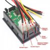
One of our projects this year is to fit solar power onto the boat. I've already got a new Victron 75/15 MPPT controller and I've just bought this little volt/amps meter. It's rated up to 30 vdc and 10 amps (ebay UK ref. 182428564437). We're 24 volts and the solar will probably only supply 8 amps flat out.
I'm a novice at electronics but eager to learn. First of all is it possible for someone to simplify the wiring connections shown in the pic. I don't want to screw it up by getting it wrong.
Also am I right in thinking that the voltage reading will be the voltage from the controller and not the voltage from the solar panels? I'm asking this because I know the voltage from the 2 x 12 volt panels wired in series will be over 30 volts in sunny conditions.
All advice and any helpful suggestions eagerly awaited.
Many thanks, Stu, Doncaster, UK

