Maker Pro
Maker Pro

Why is my relay bank not working?!?!

boyd

Oct 7, 2016
64
Joined
Oct 7, 2016
Messages
64
Part of a project I have decided the cheapest way to detect a machine has been switched on is to wire up a US$1.70 230VAC to 12VDC power supply.

Then the power supply gives a low voltage signal to a 4 channel relay bank which will then operate a couple of other items using the relay.

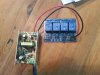
I have received two 4 channel banks off Aliexpress. The inputs are VCC, DN1, DN2, DN3 DN4 GND.

I hooked up 230VAC to the power supply. I hooked up the 12VDC positive to VCC and the negative to DN1 and several others. The LED on the relay bank comes on with the corresponding input. It all goes well but I get nothing on the relay contacts. The NC stays NC the NO stays NO. I have two banks, both do not operate

There is a VCC bridge that looks like it puts the 12VDC straight to one side of the relay. Either with it bridged or not still no result.

I have tried putting a load on the relay side, still no results.

I have tried instead of using VCC put the negative on the GND but nothing happens, no LED, nothing.

Attached is a picture. Has anyone seen these before? I am stumped where I have gone wrong. Either both units are faulty or I am missing something.

Please help. Im not a novice but gee.........

Regards
Boyd
 

Attachments

  • 20161117_174701.jpg
    20161117_174701.jpg
    353.7 KB · Views: 79

73's de Edd

Aug 21, 2015
3,622
Joined
Aug 21, 2015
Messages
3,622
Sir boyd . . . . .


. . . . . . to wire up a US$1.70 230VAC to 12VDC power supply

MAN ! . . . . .dat's CHEEEEEEEP . . . . and it still EASILY exceeds your boards power requirements, with all of its 4 relays being activated .

Initially your photo does not give referencing to the polarities of the + and - terminals of the power supply to the left.
Assuming that you have the left connection of the RED wire correct, and we can see it as being correct in its connection to the far right of the relay board.
Now shift your attention to the fact that you have placed the BLACK wire to the # 3 input of the relay board.
It needs to be moved to the far left, to the end terminal of GND.
THEN when you apply a voltage level . . . that is fitting within the units specified operating parameters ranges . . . . . to any of the 4 inputs.
That associated relay should then operate.

73s de Edd
 
Last edited by a moderator:

Harald Kapp

Moderator
Moderator
Nov 17, 2011
13,720
Joined
Nov 17, 2011
Messages
13,720
THEN when you apply a voltage level . . . that is fitting within the units specified operating parameters ranges . . . . . to any of the 4 inputs.
This is the important point: The relay board will operate the relays only when an input signal is present. Without input signal the relays will stay off.

I assume your module is this one (or a compatble one). The description says:
can be controlled directly by Micro-controller (Arduino , 8051, AVR, PIC, DSP, ARM, ARM, MSP430, TTL logic)
which means that you have to apply a voltage of either 0 V or 5 V to one of the input pins to activate or de-activate the repective relay. The description is not too specific as to which voltage turns the relay on or off. I'd expect 5 V to turn the relay on.
As you want the relays all to turn on when 12 V power is present, a simple way to achieve this is as follows:
  1. tie all 4 input pins together
  2. build a very simple '5 V generator' by using a 4.6 V zener diode and a 10 kΩ resistor connected as follows:
    zener diode anode to GND
    zener diode cathode to one end of resistor
    second end of resistor to 12 V
    This will give you ~ 4.6 V on the center tap between the zener diode and the resistor. 4.6 V is good enough for the logic on the board to detect a logic High level (you don't need the full 5 V).
  3. connect the center tap (4.6 V) to the 4 tied input pins.
When done correctly, you should hear the relays click on and off with power (12 V) plus you should see the LEDs indicate the relay status, one LED per relay.
 

boyd

Oct 7, 2016
64
Joined
Oct 7, 2016
Messages
64
Hi. Ok! I have attached what I think you are saying which is the only configuration I did not think of. Is this correct?

upload_2016-11-17_18-27-39.png
 

boyd

Oct 7, 2016
64
Joined
Oct 7, 2016
Messages
64
Oh I just saw the last reply. I actually want to be able to input 8 machines into two four-way banks. But I was unaware I needed VCC and GND powered AND then have voltage applied to each separate terminal for the corresponding relay.
 

Harald Kapp

Moderator
Moderator
Nov 17, 2011
13,720
Joined
Nov 17, 2011
Messages
13,720
No, not correct.
The inputs are suitable for TTL-Level which means max. 5 V. When you apply 12 V to them they can be destroyed.
For testing you can use a any DC voltage source between 4 V and 5 V, apply the voltae to one of the inputs and listen to the relay click. For permanent use I suggest my scheme from post #3 as a very simple solution.

Of course, it could have been even easier using a 5 V relay module and a 5 V power supply...
 

davenn

Moderator
Sep 5, 2009
14,261
Joined
Sep 5, 2009
Messages
14,261
But I was unaware I needed VCC and GND powered AND then have voltage applied to each separate terminal for the corresponding relay.

yes that is the important part

And Harald's advice about the lower voltage to switch each relay


I also edited you last post to show the circuit
it is better to avoid using pdf files that people need to open
 

Harald Kapp

Moderator
Moderator
Nov 17, 2011
13,720
Joined
Nov 17, 2011
Messages
13,720
I needed VCC and GND powered AND then have voltage applied to each separate terminal for the corresponding relay.
You could hack the module in such a way that he 12 V and GND are directly connected to teh relay coil, bypassing all other electronics on the board. You will then not be able to use the LEDs as indicators and you will no longer be able to control the relays by the inputs. No great loss as you don't use this feature anyway.

What you have to do for this:
  • find the one pin of the relay coil that is directly connected to Vcc. Judging from the image on the linked website this is the right pin as seen from top in your image in post #1
  • solder a wire to the other relay coil pin (left as seen from top, the one which has a trace to the little guy labeled Q1, Q2 etc.). Connect all the 'left' pins of teh 4 relays in this way. Then connect these to GND on the connector.
You can do all the wiring and soldering on the bottom side of the PCB. This will directly turn on the relays with applied Vcc without the need to input control signals (and also no need for the suggested zener diode-resistor combination).
If at any time you want to make use of the inputs to be able to control the relays by a signal, just remove the manually placed wires.
 

boyd

Oct 7, 2016
64
Joined
Oct 7, 2016
Messages
64
Oh and I went for 12VDC because there is at max 20m of distance between output and relay.
 

Harald Kapp

Moderator
Moderator
Nov 17, 2011
13,720
Joined
Nov 17, 2011
Messages
13,720
inputting four different 12v signals.
That's totally wrong.
GND and VCC provide the power for the whole PCB.
IN1...IN4 are used to control the on/off state of the relays. These inputs will operate from 0 V to 5 V and will draw only little current. Do not connect these inputs to 12 V!
 

Harald Kapp

Moderator
Moderator
Nov 17, 2011
13,720
Joined
Nov 17, 2011
Messages
13,720
As the saying goes: a picture is worth a thousand words:
upload_2016-11-17_9-6-30.png
This simplified schematic shows one channel of your relay module and the suggested modification for operation from 12 V without the need for control signals (inputs).
 

boyd

Oct 7, 2016
64
Joined
Oct 7, 2016
Messages
64
Hmmm. Ok. Well. I have eight separate machines. I wish each machine to have its own personal signal to each relay, independent of other inputs for a different operation for each, and also a common operation the same.

I understand how the bank works now.

So I guess I can do what you Harold has written previously although not to perform step 1 where each pin is tied but separate. So I could tie in multiple power supplies with a zener to the input for the corresponding relay I want to operate.

You see, putting a 12VDC power supply inside each machine to operate each relay was so cheap it seemed the best option. Now that I know how this bank works I wonder if I can run all the power supplies in parallel. Although what will happen if I am running two machines same time. I must draw out what I am thinking and post it. I might have to put in more components, or just a 12v zener.

I have a MUCH better idea now of where I went wrong! Just straight separate relays would have done the trick. I think you mentioned this before. I could just alter the board like you said before and separate the relays huh?
 

boyd

Oct 7, 2016
64
Joined
Oct 7, 2016
Messages
64
In all reality I should have just programmed an Arduino board!
 

Harald Kapp

Moderator
Moderator
Nov 17, 2011
13,720
Joined
Nov 17, 2011
Messages
13,720
In all reality I should have just programmed an Arduino board!
Not a bad idea, although that leaves you again with the initial issue: how do you sense teh status of each machine?
Just straight separate relays would have done the trick.
Right again. You could even have used relays with an AC coil and a voltage rating equivalent to your mains supply, These relays could be controlled by the mains power directly without the need for an intermediate 12 V power supply.
 

boyd

Oct 7, 2016
64
Joined
Oct 7, 2016
Messages
64
I just realised where it all began! I initially had the issue of how to sense the 230vac motor had been switched on and how to get that to run a pneumatic solenoid, keeping low voltage running around my shed in the open.

I didnt want to put in a 230v relay and my pneumatic solenoids which I bought and want to control were 12vdc.

Very very cheap way to run my system due to the power supplies being US$1.70, was to put one in each machine that would directly power my solenoid.

BUT.... then I came accros a solenoid bank that had half of the solenoids I needed, they were 24vdc. so I ended up buying ALL solenoids at 24vdc. But to purchase a bunch of 24vdc power supplies, they were US$3.40.......

Ha ha ha ha the dilema!
 

boyd

Oct 7, 2016
64
Joined
Oct 7, 2016
Messages
64
Ok. I have looked at this board with new eyes. There is a removable jumper from VCC to the input of the four relays. I have connected the +12dv to VCC and -VDC to GND.

If I connect any of the relay inputs to the GND I get operation of the relay.

Question: Do I still need to reduce voltage down to 5VDC for the input to the board inputs R1, R2 etc? It appears it is a 12volt board, it looks for an earth to "run" the relay.

Or...... Is the board designed to power the relays with 12VDC and power a 12VDC sensor of some type that will provide a gnd also reducing the voltage to 5VDC.

I guess I will find out soon enough if there is a wee small amount of smoke "poof" from the board lol
 

boyd

Oct 7, 2016
64
Joined
Oct 7, 2016
Messages
64
That's totally wrong.
GND and VCC provide the power for the whole PCB.
IN1...IN4 are used to control the on/off state of the relays. These inputs will operate from 0 V to 5 V and will draw only little current. Do not connect these inputs to 12 V!

Hi Harold. Mate it appears pins 1 through 4 are just looking for an earth? Well that's what is making the relays run?
 

73's de Edd

Aug 21, 2015
3,622
Joined
Aug 21, 2015
Messages
3,622
Sir Boyd . . . .

I also noticed the right side jumper clip, but the photo coverage didn't clearly show that area well enough for me to be able to ascertain its function being achieved.
I CAN easily see that there is a back emf diode across each relay coil and 1 driver transistor for each relay and
1 surface mount resistor associated with interfacing the secondary of an optical isolator used for base of the transistor of the input circuitry of each stage,
Then over on the primary of the optical isolator, there is yet another surface mount resistor associated with the primary of the optical isolator.
Yet there is still the same situation of not being able to ascertain if that circuitry was tied into ground, which would mandate the application of a typical + 5v HIGH to activate that particular relay.
Should that circuitry be connected into the + power line supply, the input lines would require a logic low . . . .or the grounding of them, as you have confirmed.
I did find from their MINIMAL spec sheet that they would like to have a nominal 20 ma current loop within any of those In 1-2-3-4 . . . .input connections.
BUT in that case THAT will be automatically accomplished by THEIR selection of installed resistor, since you are grounding the input line.
Also, at the front center you see what looks to only be 4 tinned tabs for external soldering in of wires instead of using the connector pin connections.
In not being to see them well enough, is there any chance that, instead, that they might be SM micro LEDs that light up as an input connection is made.
Which could be even made more logical if a logic LOW is needed for a relay activation input.
Any more forthcoming evaluation of the board would be dependent upon a GOOOOOOD FULL FRAME photo closeup of both sides of the board.
BTW, I was finding these boards for 99 cents.

73s de Edd
 
Last edited by a moderator:

Harald Kapp

Moderator
Moderator
Nov 17, 2011
13,720
Joined
Nov 17, 2011
Messages
13,720
it appears pins 1 through 4 are just looking for an earth?
From what you tested this is obviously the case. The description on the webpage of teh seller is absoulutely useless as it only states TTL-Logic level (0V...5V), but gives no clue as to which voltage turns the relays on, which voltage turns them off.
 
Top