Maker Pro
Maker Pro

Ultrasonic sonar

seandepagnier

Jan 19, 2018
14
Joined
Jan 19, 2018
Messages
14
I'm trying to design a schematic to drive ultrasonic transducers for pinging objects underwater (sonar) The transducers I am looking at are 40khz used for ultrasonic cleaning, and rated to 50 watts

I want to make the schematic as simple as possible while still functional. This means I don't want a lot of hardware drivers or filters if possible. Instead, the stm32 uC have fast adc so I can do filtering in software. They can easily output pwm in the desired frequencies.


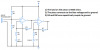
DriveA and DriveB signals are produced by the microprocessor at the right frequency as inverted waveforms with dead time.

The T1 transformer will have 15 turns for each primary, and a secondary with 100-200 turns to produce a drive voltage of 200 Vp-p to the transducer.

The resistor R2, I am not really sure the correct value, I will try with 280 ohms to start out.

The Diodes D1 and D2 are fast recovery.

The idea of the diodes D1-D4 and R3 (also not sure of optimal value) to allow measuring the millivolt returns from the transducer, but not allowing the large drive voltages into the receiver.

C2 is to balance the transformer capacitance to ground.

TR1 transformer could be an audio transformer with a few hundred turns windings, probably 1:2 ratio

The opamp is to amplify the return signal for the adc range, I can tune the gain with a screwdriver. The actual filtering (besides the simple high-pass filter) is to be done in software.

Almost all other examples I see have a lot of filters in hardware which significantly complicates the design, can this really be avoided? Filtering in software allows for changing the transducer frequency, operating at secondary resonance frequency (170khz) as well as for detecting frequency change (doplar shift) of moving targets. I can also produce waveform of variable duty cycle to reduce power consumption depending on target range.

Will this work? How could I improve it? Recommended components? Am I missing anything critical?

Would it be better to have two transducers, one for transmit, and another as receiver?
 

Attachments

  • schematic.png
    schematic.png
    14.1 KB · Views: 144

Audioguru

Sep 24, 2016
3,656
Joined
Sep 24, 2016
Messages
3,656
Are you using the receiving opamp as a comparator? It should have some hysteresis.
Many opamps do not work well at 40kHz, use a comparator instead.
 

seandepagnier

Jan 19, 2018
14
Joined
Jan 19, 2018
Messages
14
I intend to use the opamp as an amplifier because the return signals may be only a few millivolts.

I think it's wired incorrectly.. it's meant to be negative feedback.

The uC can do comparisons in software with the adc right?

Should I use a bjt instead to make an amplifier? Or just make sure I have a high speed opamp?
 

Audioguru

Sep 24, 2016
3,656
Joined
Sep 24, 2016
Messages
3,656
A pretty good opamp runs out of voltage gain at 10MHz. Then at 40kHz its gain without AC negative feedback is 100 which might not be enough. So use two opamps in series, each with a gain of 15 or 20.
 

seandepagnier

Jan 19, 2018
14
Joined
Jan 19, 2018
Messages
14
I'm afraid I'm doing something terribly wrong here...

The output from the signal transformer would be AC.. so would the negative voltages be a problem to the opamp?

When the circuit is actively driven, there could be -1 volts here (clamped from diodes). Maybe I must use a bjt amplifier instead of opamp?

These can handle the negative voltage and run faster anyway correct?
 

Audioguru

Sep 24, 2016
3,656
Joined
Sep 24, 2016
Messages
3,656
Your opamp is not powered and it is not biased so it will probably do nothing.
Usually the input of an opamp used as an amplifier is biased at half the supply voltage and has an input coupling capacitor that your circuit has. Then the output can swing up to almost the supply voltage and down to almost ground.
 

seandepagnier

Jan 19, 2018
14
Joined
Jan 19, 2018
Messages
14
I have revised the schematic.

The opamp is powered by a single side supply
 

Attachments

  • schematic.png
    schematic.png
    14.2 KB · Views: 100

(*steve*)

¡sǝpodᴉʇuɐ ǝɥʇ ɹɐǝɥd
Moderator
Jan 21, 2010
25,510
Joined
Jan 21, 2010
Messages
25,510
Rv1 seems to change the DC gain between 1 and 2. Is that what you want?
 

Alec_t

Jul 7, 2015
3,590
Joined
Jul 7, 2015
Messages
3,590
Since the wanted echo signal is likely to have an amplitude at least three orders of magnitude lower than the transmitted pulse you will need multiple amplification stages in the receiver section.
What is the purpose of R2?
 

seandepagnier

Jan 19, 2018
14
Joined
Jan 19, 2018
Messages
14
I added a stage of amplification. With two stages I should be able to amplify 500x or more.

As for the capacitor parallel to R6 (was R4), It is there to hopefully absorb any voltage spike now that I removed the isolation transformer though it is maybe not needed. Maybe the whole thing should be capacitively coupled instead??

As for R2, I am not sure again... this is why I am posting here. I found it in a reference schematic that had a similar driver. I believe the reason is to dampen the system, and avoid damaging components in case there is an issue with the transducer. It might not be needed.
 

Attachments

  • schematic.png
    schematic.png
    15.9 KB · Views: 113

Audioguru

Sep 24, 2016
3,656
Joined
Sep 24, 2016
Messages
3,656
I have not seen the spec's for your 40kHz piezo but the ones I have seen are a high impedance with a minimum load of about 50k ohms. Your parallel R5 and R6 in series with R4 create a load of only 1.5k which will be like a short across the piezo and reduce its output to almost zero. I would make R5 and R6 much higher resistance so that the load on the piezo is much higher.
R "question mark" should not connect to the input of the first opamp.

Here is a typical sonar receiver circuit:
 

Attachments

  • sonar receiver.png
    sonar receiver.png
    39.9 KB · Views: 88

seandepagnier

Jan 19, 2018
14
Joined
Jan 19, 2018
Messages
14
I have not seen the spec's for your 40kHz piezo but the ones I have seen are a high impedance with a minimum load of about 50k ohms. Your parallel R5 and R6 in series with R4 create a load of only 1.5k which will be like a short across the piezo and reduce its output to almost zero. I would make R5 and R6 much higher resistance so that the load on the piezo is much higher.
Thank you for this very helpful reply.

I see your point, and it makes perfect sense. I am not sure if 1meg ohm is the best resistance, but 1k is probably far too low. I should experiment once I get my parts.

Do you have the schematics for the drivers as well? I am very interested in combined driver/receiver schematic.
R "question mark" should not connect to the input of the first opamp.
Why should it not? I would like to understand the reason if it is really bad.

Although it might not be as good as your suggested circuit, I simulated this with ngspice, and the result is what I intend.
Here is a typical sonar receiver circuit:

This circuit is probably better than what I have. I definitely want to try it. I was worried about transformer capacitance relative to ground, but maybe this solves it by grounding the input nearest the transformer?


I might need to put a 1000-5000pF capacitor in series with the transducer. This would be to tune the circuit to resonate at the transducer frequency depending on the toroid I use, and how many turns the winding has. I'm trying to find more information on this.

I think the circuit can work even if T1 and the transducer are not tuned to resonance, but probably less efficient?

Maybe it's a problem to use the same transducer for transmit and receive? I don't see how it can resonate for receive because of the diodes. If it can resonate for receiving, wouldn't this greatly amplify my signal?
 

Audioguru

Sep 24, 2016
3,656
Joined
Sep 24, 2016
Messages
3,656
The diodes prevent the high transmit voltage from the transformer from destroying the receive opamp's inputs. The diodes do not do anything when receiving a low level echo.
 

Audioguru

Sep 24, 2016
3,656
Joined
Sep 24, 2016
Messages
3,656
The datasheet for your 40kHz piezo transducer will show its resonance. It is not an inductor needing a capacitor, its resonance is mechanical.
 

seandepagnier

Jan 19, 2018
14
Joined
Jan 19, 2018
Messages
14
My goal was to match the mechanical resonance with electrical resonance. This should provide a more efficient drive with far higher driver current/voltages through the transducer for the input power no? The duty cycle of the mosfets could be greatly reduced to produce the same amount of sound.

Since I would be powering it for many cycles (40 or more) there could be significant resonance rise.

Further, don't transducers prefer to be driven in sine wave?


As for the return signal, wouldn't the same apply? The transducer produces a 40khz signal, and if it were connected to an inductor such that it can resonate at this frequency, the return signal should also be amplified.

The problem I see, is the diodes block this return resonance, and don't help with the drive resonance either.

Please correct me if I am completely confused about this.
 

Alec_t

Jul 7, 2015
3,590
Joined
Jul 7, 2015
Messages
3,590
I suspect the mechanical resonance frequency will be modified somewhat depending on the acoustic impedance that the transducer has to drive. You may, therefore, need some dynamic tuning arrangement. Are commercial transmitter circuits self-tuned by feedback?
 
Top