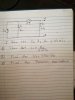
is that better? AT restor R1 I have I1 and in R2 I2, the first question is to show that I1= R2/(a+R1R2)
what I did for that is: I have one current source parallel to a resistor, so what I did is I removed the current source and I put a voltage source in a row to the R1 resistor and I did a KVL for the circuit, and I found the answer. I dont know how to find the Rthevenin and the I thevenin
Yes, I can see the subscripts now, but you reversed the direction of the independent current source and did not specify the current direction referenced by the dependent voltage source. Also you labeled the current source with two labels io and i1. That's being careless, and wastes time asking for confirmation. However, I am going to assume the current directions of your first schematic and proceed with the solution, since your exams are over by now.
First of all, I1= R2/(a+R1R2) cannot possibly be true since i1 is fed by is. Therefore, is has to be in the expression. Using the nodal method, we get.

v2 is the Vb - Va = Vth or Thevenin voltage.
I will now solve for the Thevenin parameters by three different methods. First I will find the Rth by dividing the Vth by the short circuit current, Isc. Using the nodal method again, we get.

Diving Vth by Isc gives Rth = r2(a+r1)/(a+r1+r2)
The second method is the applied source method. It consists of applying a voltage or current to the terminals and calculating the results. In this case I apply a one amp current to the terminals. The equations are.

Observe v2 above. The terms containing the independent current source, "is", comprise the open circuit voltage. The terms not containing "is" are the Thevenin resistance Rth, because the voltage was calculated with one amp applied.
The third method is the most interesting. It used the General Immittance Theorem (GIT) or Port Immittance Theorem (PIT) as it is sometimes called. See this thread
https://www.electronicspoint.com/th...quivalent-op-amp-circuit.278977/#post-1693566
From the first method we can use the equation for v2 and get the transresistance transfer equation v2/is.

Look at the denominator. The GIT says that the impedance looking to the left of r2 is a+r1. if we add r2 in parallel to a+r1, we get r2(a+r1)/(a+r1+r2), which is the same Rth we got previously. So there you have it, three ways to calculate the Thevenin Vth and Rth. Ask if you have any questions.
Ratch