Maker Pro
Maker Pro

Sony TC-WR770/870

Darryl

Sep 13, 2016
15
Joined
Sep 13, 2016
Messages
15
I was wondering if anybody could help me or point me in the right direction of the culprit which has killed full power supply in this tape deck.
This is the 2nd unit ive had this happen.
When you switch off the unit the capstan motors still run but at a reduced speed and also the rear tape lights are dim.
There is a few resistor fuses on this board R700 R702 R703
Can anybody help so i can restore full power to tge main board.

Many Thanks
Darryl.
 

CDRIVE

Hauling 10' pipe on a Trek Shift3
May 8, 2012
4,960
Joined
May 8, 2012
Messages
4,960
Hello Darryl and welcome to EP.

Sorry that no one has responded before now. Do you have a schematic?

Chris
 

Darryl

Sep 13, 2016
15
Joined
Sep 13, 2016
Messages
15
Hello Darryl and welcome to EP.

Sorry that no one has responded before now. Do you have a schematic?

Chris
Hi chris yes i do.
Ive done this to 2 machines now and i know i can fix it just knowing where the culprit is
Just got the capstans running and tape window back light lit half power
 

CDRIVE

Hauling 10' pipe on a Trek Shift3
May 8, 2012
4,960
Joined
May 8, 2012
Messages
4,960
Please post them.

Chris
 

Darryl

Sep 13, 2016
15
Joined
Sep 13, 2016
Messages
15
Hope this may help
 

Attachments

  • Screenshot_2016-09-27-11-36-27.png
    Screenshot_2016-09-27-11-36-27.png
    887.4 KB · Views: 157
  • Screenshot_2016-09-27-11-36-06.png
    Screenshot_2016-09-27-11-36-06.png
    1,002.7 KB · Views: 161

CDRIVE

Hauling 10' pipe on a Trek Shift3
May 8, 2012
4,960
Joined
May 8, 2012
Messages
4,960
Sorry, not with my old eyes. Even when I enlarge them they're just a blur.

Perhaps a skilled member with younger eyes will chime in here.

Chris
 

shrtrnd

Jan 15, 2010
3,876
Joined
Jan 15, 2010
Messages
3,876
Questionable skill and no younger eyes here.
It'd help if maybe you could make a larger pic of the power supply section schematic?
Also, unless you see some heat damage with your referenced resistors, I'd be looking more at the capacitors
as posing a potential problem here.
 

CDRIVE

Hauling 10' pipe on a Trek Shift3
May 8, 2012
4,960
Joined
May 8, 2012
Messages
4,960
Sounds like good advice from someone with questionable skills. I think you've graduated to skilled level. :)

Chris
 

shrtrnd

Jan 15, 2010
3,876
Joined
Jan 15, 2010
Messages
3,876
Maybe after another 46 years on the workbench, I'll move-up another peg to semi-skilled.
 

CDRIVE

Hauling 10' pipe on a Trek Shift3
May 8, 2012
4,960
Joined
May 8, 2012
Messages
4,960
With any luck we'll get a larger photo with the area in question circled. With 46 years to play with I think the chances are good. :p

Chris
 

73's de Edd

Aug 21, 2015
3,628
Joined
Aug 21, 2015
Messages
3,628
Sir Darryl . . . . . . .

Of your page 1 photo submitted . . . . 4th schematic page down.

I was reading the schematic fine from A18---26 down to M18---26 and
then you had just chopped off N-O-P 18 thru 26 where the vital info was
located.

Looking within the relevant portion that I can see . . . .
As per any R700----702----703---- fuses? they would have to be low value
fusible resistors and the R700 . . .etc series that I do see
are being up in the 1K regions . . .therefore they are not being fusibles.
There ARE F701 and F702 . . .1.6 A fuses.
Do you have your + and - 7.5 vdc supplies and the + 5vdc supply ?


Can you hit me with a conversation/message feature on this site to
exchange E-mail addee's and I can extract and process the relevant
schematic info to post ?

73's de Edd
 
Last edited:

shrtrnd

Jan 15, 2010
3,876
Joined
Jan 15, 2010
Messages
3,876
Nuts. 73's de Edd must have a microfiche reader to have seen that.
 

Darryl

Sep 13, 2016
15
Joined
Sep 13, 2016
Messages
15
Sir Darryl . . . . . . .

Of your page 1 photo submitted . . . . 4th schematic page down.

I was reading the schematic fine from A18---26 down to M18---26 and
then you had just chopped off N-O-P 18 thru 26 where the vital info was
located.

Looking within the relevant portion that I can see . . . .
As per any R700----702----703---- fuses? they would have to be low value
fusible resistors and the R700 . . .etc series that I do see
are being up in the 1K regions . . .therefore they are not being fusibles.
There ARE F701 and F702 . . .1.6 A fuses.
Do you have your + and - 7.5 vdc supplies and the + 5vdc supply ?


Can you hit me with a conversation/message feature on this site to
exchange E-mail addee's and I can extract and process the relevant
schematic info to post ?

73's de Edd
 

Darryl

Sep 13, 2016
15
Joined
Sep 13, 2016
Messages
15
Hi Ed sorry for the late reply as ive just restumbled on this lost webpage again lol still trying to find the problem which i still have.
i will try and get better picks.

my email is [email protected]
 

Attachments

  • 20180205_214752.jpg
    20180205_214752.jpg
    244.9 KB · Views: 107
  • 20180205_214717.jpg
    20180205_214717.jpg
    277.3 KB · Views: 121
  • 20180205_214704.jpg
    20180205_214704.jpg
    192.5 KB · Views: 106
  • 20180205_214637.jpg
    20180205_214637.jpg
    217.6 KB · Views: 112

Darryl

Sep 13, 2016
15
Joined
Sep 13, 2016
Messages
15
latest update is that this deck now has no power lol its lifeless and i need it to work again any help appreciated.
i have found my copy of the service manual with circuit diagram.
 

73's de Edd

Aug 21, 2015
3,628
Joined
Aug 21, 2015
Messages
3,628
Sir Daryl . . . . .

Referencing to the simplified schematic at the very top, first . . . . . considering that you do not have a blown R704 fusible resistor . . . . . what supply voltages do you now have ? Finding those supply points on full schematic 2.
OR confirm if you have AC output voltages at the transformer SECONDARY windings.

Aside . . . .

Ω test . . . . . testing Ω Ω Ω . . . . . . 1...Ω 2...Ω 3 . . .Ω ...testing.

REFERENCE SCHEMATIC SNIPPET OF POWER SUPPLY . . . .

ZMN2WNb.png


73's de Edd
.....
 

Darryl

Sep 13, 2016
15
Joined
Sep 13, 2016
Messages
15
What is the purpose of R700 and R703 and what component would kill power to the entire board
 

73's de Edd

Aug 21, 2015
3,628
Joined
Aug 21, 2015
Messages
3,628
Sir Daryl . . . . .

WHERE? . . . . .you . . . .g o o o o o o o o o o o o o o ?

latest update is that this deck now has no power lol its lifeless and i need it to work again any help appreciated.

If that is the case, then take ohmmeter and test across the AC cords plug to see if you are reading tens of ohms resistance of the transformers primary winding.

IF SO . . . . . . . . .


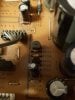
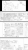
Those are being fusible resistors that will that blow open circuit, in case of excessive .overload.
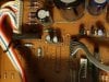
R704 at the top is a given, in its wired installation.
The lower R700 or R703's options are being incorporated in accordance to different -11,-12 or -13 board versions

Starting all over again . . . . .

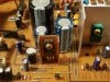
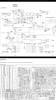
Why don't you start by using a DVM and connect its black ground lead to the central ground buss that crosses the unit .
THEN power up and check with DC metering to see if you find the bottom left corners MINUS 28 VDC supply being present.
Then move up to check for the presence of the +5 and +11 VDC supplies..
Then, move to the extreme right of the board and check for presence of the +7.5 VDC supply at the top left corner and then check the bottom right corner to see if the MINUS 7.5 VDC is present..

Clue us in on what supply is missing . . . and we can then proceed.
Sort of expecting your +5 and / or / + 11VDC to be missing.
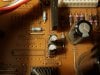
If that is the case . . .switch metering to AC mode and check for the presence of the ~15 VAC across power transformer terminals #11-13. Then stay on one lead and move one probe to #12 to see if it is reading ~ 1/2 the previous voltage being read.


73's de Edd
.....
 
Last edited:

Darryl

Sep 13, 2016
15
Joined
Sep 13, 2016
Messages
15
Well ed im here working on it now.
What actually happened i was changing ths left deck with a spare due to motor twitching even though timing marks are all correct but a couple of strands shorted on the 4 wires to motor but i did see a small flume of smoke from around those 3 pesky resistors
Now if i put dtm on dc volts black lead on start of D701 and red lead at end of R704 i get a voltage of 2.65V.

If i test either side of R703 i get 9.42V.
But no voltage on R700 and R703 these 2 are in series i guess
 
Top