Maker Pro
Maker Pro

Simple Resistance Division

tedstruk

Jan 7, 2012
476
Joined
Jan 7, 2012
Messages
476
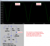
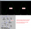
As my diagram shows, the use of a parallel resistor is used to divide the circuit, but does the resistance of the circuit change due to its inclusion?

I would have to deduce that it will effect the circuit at least a little bit. Is a the series/parallel rule or should I do a total the current and reduce the volts trick?

resistors1.JPG
 

duke37

Jan 9, 2011
5,364
Joined
Jan 9, 2011
Messages
5,364
You need to define what is input and output and where you are measuring.
In the third circuit the centre resistor is shorted and plays no part. There are two seperate resistors connected to ground.

R1 and R2 are not in parallel since the top ends are not connected together.
The top right circuit will give 50MΩ resistance if the goal is shifted to the top.

What circuit needs such super high resistor values?
 

tedstruk

Jan 7, 2012
476
Joined
Jan 7, 2012
Messages
476
This is a fuzz stomp box for an electric guitar circuit.
The local radio shack closed and I can't just run to town and get parts anymore.
The last ones I ordered from China took a month to get here. i am still waiting on potentiometers that were supposed to be here today.
The circuit is the battery side of two transistors, it calls for 2 150k resistors to the bases on the NPNs separated by a 6800 ohm resistor to the collector of the first NPN and a 10k to the collector of the other.
It would seem to me that the extra 50k is more of a guarentee that the other two resistors will fire first. Do you think that the other 50k will be missed?
I mean the circuit calls for 9v and I was thinking about arming it with a 3 pack of triple A's instead. That's a volt and a half reduction.
How can I do the math to see if it will work?

I was taught to add the total resistance of the board, and because I know the volts, I would know the rest of the equasion. Is this right or did I dream it?
 

tedstruk

Jan 7, 2012
476
Joined
Jan 7, 2012
Messages
476
Here is a break down of my sorry math..
Original Fuzz Board Total Ohms
R1-22k
R2-50k
R3-10k
R4-150k
R5-6800
R6-150k
R7-10k
R8-10k
R9-1m
R10-50k
=
1458800
Fuzz Board Total Volts
9
Fuzz Board Total Amps
6.1694543460378393199890320811626e-6


My Changes
Fuzz Board Total Ohms
R1-22k
R2-50k
R3-10k
R4-100k
R5-10k
R6-100k
R7-10k
R8-10k
R9-3m
R10-50k
=
3412000
Fuzz Box Total Volts
4.5
Fuzz Box Total Amps
1.3188745603751465416178194607268e-6

Does this board require the 1.319 amps? or does it draw that from my 4.5v source?
 

duke37

Jan 9, 2011
5,364
Joined
Jan 9, 2011
Messages
5,364
Please post a schematic otherwise all is guesswork.
I do not think anything fires. Dropping the voltage from 9V to 4.5V may have a profound effect. Post a schematic.
Do not use nunbers to over 30 places, this is absurd. You will never measure to better than 1% accuracy.
You need to specify the numbers correctly. You have interpreted 1.319μA as 1.319A. Only a factor of a million difference.:)
 

tedstruk

Jan 7, 2012
476
Joined
Jan 7, 2012
Messages
476
this is my chicken scratch.
it was in a magazine some 5 or 6 decades ago. found it in an internet search.fancyF9v.jpg
I don't have 150k's, at R4 or R5, but I do have 100k's
I don't have the 1m, I replaced it with a 3m.
The 6800 at R5 I put in a 10k.
I have 100k audio sliding log pots, and I am blocking them at 1/2 way, so they will never go over the 50K, but I need the 100k to replace the two 150k's that I dumped for 100k's.
I am waiting for some pots to finish the 1.5v version of this, but I have ramshackled this together from my spare parts... I think it will work with a 4.5v, 3AAA pack of batteries.
 

Audioguru

Sep 24, 2016
3,656
Joined
Sep 24, 2016
Messages
3,656
Your transistors have no part number so we cannot look at their datasheet.
Transistors have a wide range of hFE, the simple circuit will work only if you buy thousands of transistors and select ones with the hFE that will work in that simple circuit. You might not find any.

A transistor usually has negative feedback so it will work fine if the transistor has a low hFE or a high hFE. The transistors in that circuit have NO negative feedback.

I simulated it with a common 2N3904 transistor that has "typical" hFE. It is biased wrongly so its output is severely distorted. Then I fixed it.
 

Attachments

  • bad transistor circuit.png
    bad transistor circuit.png
    29.9 KB · Views: 87
  • good transistor.png
    good transistor.png
    32.5 KB · Views: 97

duke37

Jan 9, 2011
5,364
Joined
Jan 9, 2011
Messages
5,364
The transistors are biased for distortion as already said. Dropping the voltage will elevate the distortion maybe sufficiently to stop the amplifier working at all.
R3,R4 are critical as are R6,R7 to get the correct transistor current.
 

Audioguru

Sep 24, 2016
3,656
Joined
Sep 24, 2016
Messages
3,656
My simulation shows the poorly biased transistors barely working and without enough output to be heard.
When the circuit is biased properly then its output will be awful squarewaves (fuzz) with lots of signal level.
 
Top