Maker Pro
Maker Pro

Series pass voltage regulator not working as expected

Ehsan

Jun 12, 2014
100
Joined
Jun 12, 2014
Messages
100
I need to build a simple 0-30v 1A power supply for my lab projects.

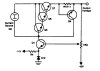
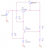
I am trying to achieve a regulation by using a darlington pair, an error amplifier transistor, negative feed and zener diode as a reference voltage.

I have built the circuit on a breadboard but when I connect a load the output voltage drops significantly!

I realized that 2N3904 transistor can not handle the current passing through it and gets burned so I replaced it with BC337 but still no satisfactory output regulation.

What am I missing here ?

Thanks for helping me out.
 

Attachments

  • regulator.png
    regulator.png
    10.7 KB · Views: 237

Harald Kapp

Moderator
Moderator
Nov 17, 2011
13,722
Joined
Nov 17, 2011
Messages
13,722
Hello Ehsan,
welcome to our forum.

The first issue I see: Q2 and Q3 do not form, as you expect, a darlington pair. Base-Emitter of Q3 is short circuited and therefore Q3 is permanently off. Remove the connection from Q3(base) to Q3(emitter). In a short simulation this regulates to within 1% for a current change from 0A...1A.

Second issue: I think Q1's emitter and collector should be swapped. When the output voltage rises, you want Q1 to draw base current away from Q2 to lower the output voltage. Your voltage divider R2/R3 therefore opens Q with rising output voltage. In your circuit the emitter of Q1 goes to the base of Q2, thus operating Q1 in reverse mode with much lower gain.
 
Last edited:

Ehsan

Jun 12, 2014
100
Joined
Jun 12, 2014
Messages
100
Thanks for the reply Herald:

Actually I made those mistakes when I wanted to quickly draw the circuit in Orcad to post it here, but my circuit in breadboard has been setup correctly. I updated the circuit diagram and added a load of 15 Ohm anyway. In Orcad simulation everything is fine as you see the output voltage does not drop and stays at around 15v while supplying around 1A of current.

But in reality (not simulation) the output voltage drops to 9v and the current does not exceed more than 0.6A.

One thing that I noticed is that after connecting the load the collector current of Q1 drops to zero(from 3mA). Does it mean that I have to let more current pass through R1 (by reducing the resistance of R1)?

I am so confused because when IC1 drops to zero I expect the base current of Q2 increase (IR3 = IB2 + IC1) , but surprisingly the base current of Q2 drops from 2.9ma to 2.0mA and then goes back to original 2.9mA ! By the way Q2 is becoming very hot in less than 2 seconds.

Any opinions ?
 

Attachments

  • regulator_updated.png
    regulator_updated.png
    14.4 KB · Views: 218

KrisBlueNZ

Sadly passed away in 2015
Nov 28, 2011
8,393
Joined
Nov 28, 2011
Messages
8,393
If Q2 is overheating, make sure Q3's collector is connected properly.

I would replace Q2 and Q3 with a single Darlington transistor such as a TIP120 (TO-220 package) or at least a BD679 (TO-126 package the same as the BD139 you're currently using as Q3). It will also need a significant amount of heatsinking - the voltage across it will be 33V - 15V = 18V so at 1A output current it will be dissipating 18W so you want a heatsink with a thermal resistance of 3°C/watt or less.

If you haven't fixed the problem, upload a picture of your breadboard construction.
 

Harald Kapp

Moderator
Moderator
Nov 17, 2011
13,722
Joined
Nov 17, 2011
Messages
13,722
For one: Increasing the base current to Q2 could help. But I'm irritated by Q2 becoming hot. It shouldn't. Check the connections of Q2 and Q3, check the voltages across C-E of both transistors.

What happens to V1 when you apply the load? Does it stay at 33V?

Kris, you beat me by a few seconds :)
 

Ehsan

Jun 12, 2014
100
Joined
Jun 12, 2014
Messages
100
Alright I got it working, I got confused by the pin-outs of BD139. That is why Q2 was becoming hot. (0.6A of current collector were going right through it) I switched the pins of BD139 and added 2N3055 as a pass transistor. It works.

Now I am observing this behavior :

I have set the regulated output to 15.09v, I applied a load of 15Ohm and I got 1A current. But the regulated output instead of dropping, increases to 15.26v. That is 1.13% increase. This increase happens in all level of voltages. Is this normal ? If it is not then how can I counter it ?

By the way the unregulated voltage drops from 33v to 24.42v when I suck 1A of current. (my transformer is 24v-0-24v rated at 2A and I am using full bridge rectifier.)
 
Last edited:

Ehsan

Jun 12, 2014
100
Joined
Jun 12, 2014
Messages
100
I also observed that when I consume 1A of DC current (after rectifier bridge) the current in secondary wingdings of my transformer goes up to 1.5A (that's AC current) but I think I should ask about this in a new thread.
 

KrisBlueNZ

Sadly passed away in 2015
Nov 28, 2011
8,393
Joined
Nov 28, 2011
Messages
8,393
No, it's not normal for the regulator output to increase as you increase the load. Normally it will drop slightly with increasing load current.

How much smoothing capacitance do you have after the bridge rectifier? A rule of thumb is 1000 µF per amp of load current, but I would use more than that.

Do you have an oscilloscope? Check the level of ripple going into the regulator. The more current you draw, the further it will dip. If it dips below about 18V the regulator will be losing regulation. You would expect this to cause a drop in the output voltage but depending on the behaviour of the regulator that's not necessarily the case.

No, don't start a new thread. A different problem with the same circuit should go in the same thread, because earlier postings can be relevant.

Can you upload a photo of your construction? Show us where you connect the load resistor and the multimeter.
 

Ehsan

Jun 12, 2014
100
Joined
Jun 12, 2014
Messages
100
The ironing capacitor is 3300uF, 50v. Using the Oscilloscope the max voltage ripple peak to peak Vpp is 1.6v

It was hard to take a picture showing Voltmeter and Ammeter in place ( their connecting wires are long) but Ammeter is in series between 2N3055 emitter and the load. and voltmeter two probes one grounded and positive one is connected to the non grounded side of the load.

Sorry but I've already started a new thread ( I read your comment after that) maybe you can merge it over here or just leave it there.
 

Attachments

  • breadboard.jpg
    breadboard.jpg
    164.3 KB · Views: 217
Last edited:

Ehsan

Jun 12, 2014
100
Joined
Jun 12, 2014
Messages
100
In order to get the output voltage down to zero I used this trick (I attached the circuit : "down to zero.jpg"). After applying the negative voltages, that problem of rising output voltage after applying a load is gone! Now the voltage decreases lol

But regulation performance is 3.7% ! It's not good quality. Do you guys think will it boost the regulation performance if I place a current source in place of R1?


reference : http://www.tequipment.net/assets/1/26/Documents/xp-650.pdf
 

Attachments

  • orcad_circuit.jpg
    orcad_circuit.jpg
    46.8 KB · Views: 183
  • down to zero.jpg
    down to zero.jpg
    25.8 KB · Views: 186

Harald Kapp

Moderator
Moderator
Nov 17, 2011
13,722
Joined
Nov 17, 2011
Messages
13,722
Your circuit is getting more and more complex. Have you considered using an integrated regulator like the LM317? (http://www.ti.com/lit/ds/symlink/lm317.pdf)
Figure 2 in the datasheet shows an application for 0V...30V output and the IC is suitable for up to 1.5A (cooling/heatsink required).
Figure 14 cshows a boost circuit for even more output current.
 

Ehsan

Jun 12, 2014
100
Joined
Jun 12, 2014
Messages
100
No I don't want to use IC regulators. They are not good for real adjustable bench power supplies, plus I want to learn ! I can easily put one of those LM317 regulators with two resistors and two capacitors and get a working power supply but where is the fun then ?

I can even go to the market and buy an already well designed and decent power supply ! But will I learn something?

Surely not.
 

Ehsan

Jun 12, 2014
100
Joined
Jun 12, 2014
Messages
100
Ok I added the current source.

Now no load regulated voltage have been set to 15.04v, then I add a load of 15 Ohms and I can get full 1A current, but the regulated voltage goes down to 14.71v.

That is 2.2% regulation. Still not good.

Where should I probe for problems ?
 

LvW

Apr 12, 2014
604
Joined
Apr 12, 2014
Messages
604
"better amplifier" means: Much more gain. Thus, the sensitivity to error voltages is considerably improved. However, watch the stability properties because larger loop gain reduces the phase margin.
 

Ehsan

Jun 12, 2014
100
Joined
Jun 12, 2014
Messages
100
Ok I got it working !

This article is really brilliant : http://tangentsoft.net/elec/opamp-linreg.html ; I remember reading this a year ago or so.

By reading that article I realized that one can feed the Zener voltage reference from the regulated side and not the unregulated one.

My unregulated side was providing 50mA to keep the Zener diode at it's intended Zener voltage. When I got rid of that 50mA all of a sudden my regulation quality jumped to 0.5% ! and that is while I was sucking 1A of current.

ok now it's working perfectly, but I wanna know why consuming only 50mA from unregulated side has this huge negative impact on regulation? What is going on here ? lol

I don't think an amplifier is necessary now. I am satisfied with the result. The next step is implementing a current limiting mechanism.
 

Harald Kapp

Moderator
Moderator
Nov 17, 2011
13,722
Joined
Nov 17, 2011
Messages
13,722
I wanna know why consuming only 50mA from unregulated side has this huge negative impact on regulation?
It is not the 50mA, if they were constant. They arent: it is the change in the unregulated voltage that leads to a change in zener current (via the series resistor to the zener diode) which in turn leads to a change in zener voltage and consequently to a change in output voltage.
 

Ehsan

Jun 12, 2014
100
Joined
Jun 12, 2014
Messages
100
Awesome ! I got it.

I think the admin of this forum must provide a link to a Paypal account so those who got their problem solved, and feel happy and excited about it can show their gratitude by sending donations: 1$, 5$, 10$ 100$ 10000$ ! who knows how much people are willing to be thankful !
Anyway it should not be mandatory; just like if you feel it then you can donate.

I personally was going to spend like 40$ to buy a book only to read one of its chapters on voltage regulation and I feel I saved that money by having you guys helping me.

I'll let you guys know when I get stuck in current limiting circuits....
Cheers.
 

Harald Kapp

Moderator
Moderator
Nov 17, 2011
13,722
Joined
Nov 17, 2011
Messages
13,722
Glad you're glad :)
We don't do this for money, just for the fun of it.
 

Ehsan

Jun 12, 2014
100
Joined
Jun 12, 2014
Messages
100
Ok I got the current limiting circuit in place (It was easier than I thought) and everything is working as expected.

But there is one problem: when I switch off the transformer power in, the output regulated voltage takes time to get to zero (really slow). I think it is because of those big ironing capacitors. What can I do to make the output drop to zero instantly ?

What came to my mind was to put a permanent load resistor, but I am not sure if it is the right approach.

Any opinion ?
 
Top