(thinks...)
So the beam needs lots of mass to counter disturbances from air movement, but a heavy beam tends to bend the pole it depends from so you are forced to adjudicate a trade-off.
yes it is a tradeoff, most amateur systems use less that 1kg, many 0.5 kg or less and then house the unit is a relatively airtight enclosure... styrofoam box, inverted glass or perspex fish tank ( ya can still see the beast then
)I have revised my one down to 1kg max. The other big problem is ....
yes the heavier mass is more stable BUT its much much harder to dampen the oscillation than with a very light mass.
And that is where I am currently having a crap of a problem trying to sort out. by the end of saturday nite I was about ready to scrap the whole thing !!!
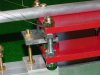
its a hell of a job getting the dampening to work. currently have a couple of rare earth magnets with the aluminium "blade" passing betyween them and its just not doing anything. The boom just continues to merrily oscillate. I have to get the dampening strong enough to stop the oscillation within 1 to 1.5 cycles.
The guys are saying that the strength of the magnetic field needs to be such that I can feel strong resistance to passing the aluminium through it by hand. its proving really difficult to achieve.
I find it hard to get past my jewelled bearing. Amethyst crystals terminate in sharp pyramids which could provide vertical support too, against a dimple in a suitable surface.
It is a bit surprising that something as flexible as aluminium is used. It would have been less surprising to me if you used rock for both the supporting and the oscillating elements of the seismometer.
some guys use angle iron or even galvanised piping. But a reasonably sturdy aluminium frame isnt any real problem.
Dave