Maker Pro
Maker Pro

Repairing a burned-out Flash Unit (screenprinting)

DeadworlD

Jul 5, 2018
5
Joined
Jul 5, 2018
Messages
5
I have a 20x24 flash unit. It is basically a big oven burner. It uses an Omron E5C4-R Temperature Controller and it was wired into a JGX-1 A4840 SSR which controlled a simple LED light and a large oven like coil to produce heat for flash drying ink on a screen printed t-shirt.

I was forced to delve into this because the SSR caught fire and melted. Not a fun thing.

So I looked around but could not find the same SSR available in the US so I found one that APPEARS to be the same: MGR-1 A4840. I googled as mcuh as I could looking for comparisons to see if it would be a compatible replacement for the original SSR. The specs all read the same as far as I could tell so I went with it.

I did take some pictures of the original connections but it was so convuluted that I can no longer be sure I am anywhere close to wiring this correctly.

My problem is this: When I try to wire it up the way it appears in my pictures and how the data sheets read to me I can't get this to work, this being the Temperature Controller to trigger the SSR to turn on/off according to temperature.

1) I purchased the MGR-1 A4840 SSR to replace the original JGX-1 A4840 SSR
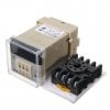
2) I purchased a replacement E5C4-R K 0-399 to replace the original of the same model
3) I purchased a replacement thermocouple

Assuming the melted SSR may have damaged the Temp Controller I wanted to replace both. I can get the Temp Controller to power up and read the thermocouple just fine. The issue comes in wiring the control from the Temp Controller to the SSR.

I have been looking at this issue for so long my eyes are crossed and my brain is fried.

Attached are pictures.

There is a 4 prong rocker switch, an LED lamp/light, the SSR, the Temp Controller, and the heating element. If someone could help me in figuring out how to re-wire this I would be most appreciative. I assumed that the Output voltage would trigger the SSR but I do not get any voltage at all from what I read as the Output on the Temp Controller.

THANKS in advance for any help you can provide.


MGR-1 A4840 Temperature Contoller Solid State Relay AC 24-480V 40A
Specification:

Product Name Solid State Relay
Type MGR-1 A4840
Input AC 70-280V
Output AC 24-480V 40A 50/60Hz
Relay Size 5.7 x 4.4 x 3.1cm/ 2.3" x 1.8" x 1.2"(L*W*T)
Material Metal, Plastic, Electric Parts
Main Color Silver Tone, Black, Clear
Weight 100g
Package Content 1 x Solid State Relay
Description:

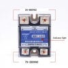
  • Feature single phrase, this Solid State Relay is ideal for automatic process control application, a must component for temperature controller and other machinery control system.
  • High reliabily, compact size, a great part for temperature controller and other machinery control system.

Flash-Dryer-Parts-Diagram.jpg SSR-MGR-1-A4840-40A-AC-AC.jpg OMRON E5C4-R.jpg
 

Attachments

  • E5C4.pdf
    178.4 KB · Views: 166

kellys_eye

Jun 25, 2010
6,514
Joined
Jun 25, 2010
Messages
6,514
The SSR you show is a 'Cheap Chinese knockoff' - Youtube experimenters have dismantled these things and discovered that the switching device is usually well UNDER-rated for the actual spec of the SSR i.e. they use 25A triacs but label them as 40A......

What is the actual power consumption of the load? (20x24 flash)
 

73's de Edd

Aug 21, 2015
3,622
Joined
Aug 21, 2015
Messages
3,622
Sir DeadworlD . . . .

Taking your info initially supplied info , along with a little added markup and additional info, and then collecting it into one area . . . we now have *****:

The bottom info is the internal explanation of the contents of your MGR-1 A4840 Solid State Relay, that handles the REAL power that gets fed to the lamps.
On your FLASH DRYER WIRING DIAGRAM , it gave absolute minimum information, other than the controls.
I just then connected the required power after the double pole switch into the EC54 controller, AND . . . YOU . . . must have the pins 1-2-3 thermocouple connections placed correctly .
What we don't know is the pins 4-5-6 connections adjunct wiring, its routing and any support components.
What we can ascertain is that circuitry is being there and correct and ends up at the YELLOW BOX connection I have placed under the SSR.

Since your SSR is the A version it is expecting anywhere from 70--240 AC volts to be there to trigger it into its on state.
BUT it is only needing in the order of a mere 5 ma of current. Therefore there must be some 50K or so of resistance in the path to limit the AC power on down to that feeble of a level.
What you need to do now is connect up a DVM in its AC mode and place in a range just above 240 volts AC . . . . . . ..unless it is autoranging . . . to the terminals that were initially going to the input of the SSR which I have now YELLOW BOXED.
If you have the AC power present and the switch, on we hope that you will be finding AC activation power at the SSR input terms being tested. If the SSR has then given power to the lamps, the thermocouple would be changing with heat build up until its trip threshold where the normally closed contacts between 6 to 4 would flip to 4 to 5 and thereby disrupt power to your heat lamps, until the heat level drop period detected by the thermocouple detected the need to flip the relay contacts back to 6 to 4 and start heating for a prescribed warming time again.

Initially . . . . just see if the AC triggering voltage into the primary of the SSR is obeying its proper on off protocol, by the SSR relay secondary switching action in activating the lamp bank.
If it is not now powering up the lamps, the thermocouple can be fooled into cycling, by the heat of an incandescent lamp heat against it or a heated blow dryer, directing a warming airstream upon it .
If not, we will have to check out the controllers Pin 4 to 5 to 6 switching relationships.

ASIDE . . . .
You can get the REAL SSR's from Digi Key or Mouser
I must have 8 or so of them, but mine are all 3-24VDC activation voltages.
One Gordos, two Irrational Rectumfire and 5 Crydoms. My last ones I utilized were to replace the black pitted electromechanical contactor assembly on my 4 ton refrigerated air conditioner.
Those, with my whole house SURGE SUPRESSOR BLOCK, located nearby, should keep me going flawlessly, well on past my expiration dating.


What say you now . . .?

***** TECHNO REFERENCING ***** . . . . .

upload_2018-7-5_6-35-58.png

73's de Edd
.....
 
Last edited:

DeadworlD

Jul 5, 2018
5
Joined
Jul 5, 2018
Messages
5
The SSR you show is a 'Cheap Chinese knockoff' - Youtube experimenters have dismantled these things and discovered that the switching device is usually well UNDER-rated for the actual spec of the SSR i.e. they use 25A triacs but label them as 40A......

What is the actual power consumption of the load? (20x24 flash)
I wish I knew more about all of this. This is only my first foray into this field. I have only a rudimentary understanding of all of this. How would I test for the "actual" load? The specs for the Flash Unit are as follows:

Flash Dryer 18x18 Inch 2000w with Temperature Display Adjustable Stand T-Shirt Curing with Wheels Easy to Move

This is a professionally flash dryer 18”x18”,2000w .Adjustable stand from 30" to 48" ,360-degree level swivel head for easy use,and base with wheels easy to move. The temperature is over 400 degrees F at distance of 2 1/2" below the flash heating element. It can easily cure plastisol ink for silk screen with a natural fluctuations in the temperature printing.

Features (truncated to just power related)

Flash dryer input: 110v/60Hz /Power: 2000 Watts

Average Current Draw: 13 Amps

Maximum Current Draw: 16.5 Amps

Average Power Usage: 1350 Watts

Maximum Power Usage: 2000 Watts

Input Power: 110V/60Hz

Hope that helps answer the question. Thanks.
 

DeadworlD

Jul 5, 2018
5
Joined
Jul 5, 2018
Messages
5
Sir DeadworlD . . . .

Taking your info initially supplied info , along with a little added markup and additional info, and then collecting it into one area . . . we now have *****:

The bottom info is the internal explanation of the contents of your MGR-1 A4840 Solid State Relay, that handles the REAL power that gets fed to the lamps.
On your FLASH DRYER WIRING DIAGRAM , it gave absolute minimum information, other than the controls.
I just then connected the required power after the double pole switch into the EC54 controller, AND . . . YOU . . . must have the pins 1-2-3 thermocouple connections placed correctly .
What we don't know is the pins 4-5-6 connections adjunct wiring, its routing and any support components.
What we can ascertain is that circuitry is being there and correct and ends up at the YELLOW BOX connection I have placed under the SSR.

Since your SSR is the A version it is expecting anywhere from 70--240 AC volts to be there to trigger it into its on state.
BUT it is only needing in the order of a mere 5 ma of current. Therefore there must be some 50K or so of resistance in the path to limit the AC power on down to that feeble of a level.
What you need to do now is connect up a DVM in its AC mode and place in a range just above 240 volts AC . . . . . . ..unless it is autoranging . . . to the terminals that were initially going to the input of the SSR which I have now YELLOW BOXED.
If you have the AC power present and the switch, on we hope that you will be finding AC activation power at the SSR input terms being tested. If the SSR has then given power to the lamps, the thermocouple would be changing with heat build up until its trip threshold where the normally closed contacts between 6 to 4 would flip to 4 to 5 and thereby disrupt power to your heat lamps, until the heat level drop period detected by the thermocouple detected the need to flip the relay contacts back to 6 to 4 and start heating for a prescribed warming time again.

Initially . . . . just see if the AC triggering voltage into the primary of the SSR is obeying its proper on off protocol, by the SSR relay secondary switching action in activating the lamp bank.
If it is not now powering up the lamps, the thermocouple can be fooled into cycling, by the heat of an incandescent lamp heat against it or a heated blow dryer, directing a warming airstream upon it .
If not, we will have to check out the controllers Pin 4 to 5 to 6 switching relationships.

ASIDE . . . .
You can get the REAL SSR's from Digi Key or Mouser
I must have 8 or so of them, but mine are all 3-24VDC activation voltages.
One Gordos, two Irrational Rectumfire and 5 Crydoms. My last ones I utilized were to replace the black pitted electromechanical contactor assembly on my 4 ton refrigerated air conditioner.
Those, with my whole house SURGE SUPRESSOR BLOCK, located nearby, should keep me going flawlessly, well on past my expiration dating.


What say you now . . .?

***** TECHNO REFERENCING ***** . . . . .

View attachment 41860

73's de Edd
.....

I apologize for providing a blank layout of the components. I did this for myself to try and document how it had previously been wired so I could recreate that.

Yes, this is a cheap chinese unit but my hope is to use the case and replace the cheap parts to make a better unit. Specifically I wanted to replace the burner element with an IR element of similar size.

Thank you for the updated diagram. That is exactly how I thought it should be wired, but what I can't figure out is why the Temp Controller has no current output (on 4,5) to power the SSR. Is a load required on the SSR for testing purposes? There is suppoesed to be current of some form to trigger the SSR on/off correct?

I have the majority of the components (sans Burner) on my work table so that I could determine how this works prior to wiring everything up in the actual unit.

Thanks again for your input/help on this.
 

kellys_eye

Jun 25, 2010
6,514
Joined
Jun 25, 2010
Messages
6,514
Maximum Current Draw: 16.5 Amps
This is the key specification. It's always wise to over-rate any switching device to provide a safety margin and 50% is a good place to start which means you need an SSR that can cope with 25A MINIMUM.

As mentioned, although 'marked' as 40A SSR's, many of the Cheap Chinese knock-offs are under-rated and the 40A version commonly has a 25A switch...... although this seems adequate for the 50% margin I specified you can't even be sure that the 25A device is going to be genuine.

The short answer is to purchase a device from a known reputable seller such as Digikey, Farnell, RS Components etc where (hopefully!) their quality control will keep the trash from reaching the customer. i.e. get a 40A version from one of those noted.
 

73's de Edd

Aug 21, 2015
3,622
Joined
Aug 21, 2015
Messages
3,622
the Temp Controller has no current output (on 4,5) to power the SSR.

Is a load required on the SSR for testing purposes?
No . . . . unless you want to jury rig up an incandescent lamp load in series with with 120VAC to then be able to visually confirm the SSR secondary's operation.

There is supposed to be current of some form to trigger the SSR on/off correct?
That's for certain.

How about having the unit totally AC power input free and use an ohmmeter to measure between the left terminal of the
SSR left input to pins 4-5-and 6 for the amount of circuit resistance in all possible paths .
Then do the same for the SSR right input to pins 4-5-and 6.
Then measure from the HOT AC wire, to see if it is directly connected to pin 7 or 8 of the E5C4, and then over to pins 4-5-and 6.to see how they are getting AC.
Report back if 7 or 8 is directly / or / resistively connected to BROWN / HOT AC line.

73's de Edd
.....
 

DeadworlD

Jul 5, 2018
5
Joined
Jul 5, 2018
Messages
5
Thanks for all of the input. After much hair pulling I popped in the OLD temp controller and everything worked. Apparently both of the replacement temp controllers I purchased are either a) faulty [they are from china], or b) some other version withe different specs that is exactly the same model as my OLD one. I'm going with answer A. LOL

So the wiring was all correct, but the temp controllers would not work as expected by routing the AC.

Thanks again to everyone and I'm sure I will be back with more issues as I delve further into fun world of electronics.
 

DeadworlD

Jul 5, 2018
5
Joined
Jul 5, 2018
Messages
5
No . . . . unless you want to jury rig up an incandescent lamp load in series with with 120VAC to then be able to visually confirm the SSR secondary's operation.


That's for certain.

How about having the unit totally AC power input free and use an ohmmeter to measure between the left terminal of the
SSR left input to pins 4-5-and 6 for the amount of circuit resistance in all possible paths .
Then do the same for the SSR right input to pins 4-5-and 6.
Then measure from the HOT AC wire, to see if it is directly connected to pin 7 or 8 of the E5C4, and then over to pins 4-5-and 6.to see how they are getting AC.
Report back if 7 or 8 is directly / or / resistively connected to BROWN / HOT AC line.

73's de Edd
.....
I will try that. I found, after inserting old temp controller, that both of the new units I purchased are defective. Everything worked as expected when I popped in the old temp controller. Wiring is correct. New units defective. ut will take your advise above and test them. Thanks.
 

73's de Edd

Aug 21, 2015
3,622
Joined
Aug 21, 2015
Messages
3,622
Sir Rooster man . . . . . . (and thats with you being the 363rd variant thereof)


Are any similar / like units to be found within these ?
https://www.google.com/search?q=Replacement+heater+element+for+18x18+Inch+2000w+element+for+t+shirt+"FLASH"+dryer"+dryer&sxsrf=AOaemvJDqLFOs7wM7O_et20pdoDsdUvYEQ:1634944359182&source=lnms&tbm=isch&sa=X&ved=2ahUKEwiok4aukt_zAhXznGoFHb6lC8YQ_AUoAnoECAEQBA&biw=1920&bih=969&dpr=1

Of those, top line . . . . the $255.00 unit . . . .vendor, I suspicion of being a rapist.
Oven bake /broil Calrod elements *** don't even approach that high pricing level.
And you are only heating up to a fraction of that MAX capacity, anyway.
*** Matter of fact, find an appliance repairman's back yard horde / stash of old stove / ovens and one could be found for a mere pittance.

Plus, with your not having provided ANY info on your unit, view to see if this might relate.


Also, why not additionally check out a dedicated Tee-shirt / screen printing forum for their experiences

https://www.t-shirtforums.com/threads/flash-dryer-not-reaching-full-power-at-home.182795/

Thaaaaaaaaaaaaaassit . . . . .

73's de Edd . . . . .


EXTREMELY SEVERE WIND, LIGHTNING and THUNDERSTORM:
A chance to see just how many family members can fit into one bed.


.


.
 
Last edited:

Rooster363

Oct 22, 2021
2
Joined
Oct 22, 2021
Messages
2
I'm also looking for the temp gauge part number this one in the picture I have posted

Sir Rooster man . . . . . . (and thats with you being the 363rd variant thereof)


Are any similar / like units to be found within these ?
https://www.google.com/search?q=Replacement+heater+element+for+18x18+Inch+2000w+element+for+t+shirt+"FLASH"+dryer"+dryer&sxsrf=AOaemvJDqLFOs7wM7O_et20pdoDsdUvYEQ:1634944359182&source=lnms&tbm=isch&sa=X&ved=2ahUKEwiok4aukt_zAhXznGoFHb6lC8YQ_AUoAnoECAEQBA&biw=1920&bih=969&dpr=1

Of those, top line . . . . the $255.00 unit . . . .vendor, I suspicion of being a rapist.
Oven bake /broil Calrod elements *** don't even approach that high pricing level.
And you are only heating up to a fraction of that MAX capacity, anyway.
*** Matter of fact, find an appliance repairman's back yard horde / stash of old stove / ovens and one could be found for a mere pittance.

Plus, with your not having provided ANY info on your unit, view to see if this might relate.


Also, why not additionally check out a dedicated Tee-shirt / screen printing forum for their experiences

https://www.t-shirtforums.com/threads/flash-dryer-not-reaching-full-power-at-home.182795/

Thaaaaaaaaaaaaaassit . . . . .

73's de Edd . . . . .


EXTREMELY SEVERE WIND, LIGHTNING and THUNDERSTORM:
A chance to see just how many family members can fit into one bed.


.


.
 

Attachments

  • Screenshot_20211102-203500.png
    Screenshot_20211102-203500.png
    365.4 KB · Views: 2

73's de Edd

Aug 21, 2015
3,622
Joined
Aug 21, 2015
Messages
3,622
Sir Rooster363 . . . . . . . . . . my continuance

Oh h h h h ( sorrowful, woeful sound) . . . . . .good Lord . . . . . . for THAT exact unit ! . . . . .then, be prepared to take out a second mortgage lien against your house.
Check out . . . just like 'ole tee shirt dude did . . . . and see if time of use and high current passage has either oxidized a wire or its terminal connection at the 8 screw terminals of that plug in relay, over on the side.
Or, also check the expected 6 relay contacts inside of the plug in relay to the right side, for being blackened / pitted / worn / eroded / arcing.
(With the other two connections being for the relay coil ).
With this being a commercial grade relay, the outer relay housing is suspect to be clear and thereby be viewable thru it.
Also unplug and check out all of the 8 octal pins of the relay, to see if any pin has had heavy current passage . . . .thru such a small gauge( ~22 ga) of solid copper wire . . . .developing a floating wire connection and just having fractured / crystallized solder surround, about it..
Finally, use an ohmmeter, with the unit having NO AC power connected, for positive testing of circuit continuity and then switch metering to AC volts function, of an adequate higher voltage range, to be able to check power flow under powered up conditions.
Also listen for, or visually see your relay armature clicking / responding / moving . . . . . on it's powered up activation.

Finally, exactly, what does your units heating element ohm out, between its ? probably ? 2 to 4 ? . . . . . connections ?

Thaaaaaaaaaaaaassit . . . . .

73's de Edd . . . . .

Tell me this . . . . .
On my phone ? Why do I have to press one for English, when they are then just going to transfer me to someone that is then going to be S O O O O O O O heavily accented, that I then wouldn't be able to understand them anyway ?


.
 
Last edited:
Top