Maker Pro
Maker Pro

Ray Jefferson Model 155 Marine Battery Charger

johnbkobb

Mar 11, 2014
14
Joined
Mar 11, 2014
Messages
14
Its vintage is circa 1989 according to the PC board inside. I have no schematic for it so I am in the process of trying to draw one with Free "Express PCB Electronics Design Software". I'm having a few problems though. I really do not know everything there is to know about electronics.
Some of the components on the board I cannot identify so I look for the numbers and google them and download the datasheets if I can find them and look for their electronic diagram. In the components list in the program many of the components are not listed, but some are.

My question is does anyone use this program for circuit design? I'm not an engineer, just a retiree trying to learn a little more about electronics and keep myself busy. Is there another free program like this that would be more user friendly. I've tried to use Proteus 8 Demo but after all the work I did with trying to make a schematic of the Model 155 I found out that the save function in the Demo was turned off so I lost everything and wasted a whole day teaching myself about something I'll never pay for and use.

Any suggestions wuold be appreciated. Hope this is the right forum, sorry if it's not.

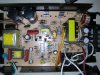
Pics - PCB Component side, PCB Soldered side, Schematic Diagram I'm trying to make as yet unfinished

Thanks,

John
 

Attachments

  • Bad Ray Jefferson Model 155 (1).jpg
    Bad Ray Jefferson Model 155 (1).jpg
    152.2 KB · Views: 864
  • Ray Jefferson Model 155 Circuit Board Solder side (1).jpg
    Ray Jefferson Model 155 Circuit Board Solder side (1).jpg
    149.7 KB · Views: 642
  • Model 155 Schematic.jpg
    Model 155 Schematic.jpg
    82 KB · Views: 681
Last edited:

(*steve*)

¡sǝpodᴉʇuɐ ǝɥʇ ɹɐǝɥd
Moderator
Jan 21, 2010
25,510
Joined
Jan 21, 2010
Messages
25,510
Is this a power supply you're trying to fix?

It looks like there have been some attempts already.

Tracing out the circuit would not be my #1 priority in this case.
 

johnbkobb

Mar 11, 2014
14
Joined
Mar 11, 2014
Messages
14
It's a marine battery charger that will charge 3 banks of 12V batteries. Original problem was low voltage at the 3 + outputs 11.XX V won't charge a 12V battery. Used to have about 14.4 V. While I was messing around with it I blew the 3 A fuse (the one closest to the 120VAC input. Now if I put a fuse in it it blows immediately, so I now have 2 problems. Other than the fuse missing nothing has been replaced.
 

(*steve*)

¡sǝpodᴉʇuɐ ǝɥʇ ɹɐǝɥd
Moderator
Jan 21, 2010
25,510
Joined
Jan 21, 2010
Messages
25,510
OK, there are several things to check.

First, it sounds like you have caused one or more of the semiconductors to fail short circuit. You've mentioned getting the datasheets, the devices are likely to be either mosfets or double diodes.

The low voltage problem *may* simply be due to dead capacitors. I note some brown gunk on the board near the capacitors. WHilst this *may* be glue or something else, it looks a lot like electrolyte. There's only 6 electrolytic capacitors on the board. It may pay to replace them all. Note that the ones near the outputs are likely to be low ESR types.
 

johnbkobb

Mar 11, 2014
14
Joined
Mar 11, 2014
Messages
14
There are 2 IRF830 N Channel Power MOSFETs (Q1 and Q2) how can I check them? Should they be removed to check them? I have a cheep ($50) Micronta DVOM that was purchased many years ago from Radio Shack and an old Tektronix 2213 60 MHz o'scope that my brother gave me a few years ago.
As far as the capacitors go how can you tell if those capacitors are low Equivalent Series Resistance (ESR) type? Did they have these 25 years ago when this charger was made? How can I check?
Some of the replacement caps are smaller in H & D but have the same Capacitance, Voltage, and Temperature ratings. I'm assuming that the smaller size will work just fine as long the leads will go through the board holes.
I think the brown residue at the bottom of the big caps is an adhesive as all the big caps have it and it doesn't smell like a bad cap.
What is the difference between a 104 and a 104z ceramic disc cap?
 
Last edited:

(*steve*)

¡sǝpodᴉʇuɐ ǝɥʇ ɹɐǝɥd
Moderator
Jan 21, 2010
25,510
Joined
Jan 21, 2010
Messages
25,510
In circuit, check the resistance across each of the pins of the mosfets. You're expecting to see some form of diode action across 2 of the pins, and them being insulated from the third pin (gate). The circuit will affect this, but if you see suspiciously low resistances then it's time to take it out and test it.

Generally speaking a capacitor that is physically smaller despite the same capacitance and voltage rating will be rated for lower ripple current and/or have a higher ESR. (It may also have a lower temperature rating or a lower lifetime)

The output capacitors on a switchmode regulator are where you will typically find/use low ESR capacitors. Capacitors these days are likely to be smaller and better than 25 years ago. Go for 105C rated capacitors as a preference

104 and 104z have the same capacitance, the z may be a tolerance. 0.1uF +80%/-20%. the one without the tolerance specified is probably more accurate :) You may be hard pressed to find a capacitor with such a wide tolerance these days. More important will be the voltage rating.
 

johnbkobb

Mar 11, 2014
14
Joined
Mar 11, 2014
Messages
14
Pins Q1 (IRF 830) Q2 IRF 830

1-2 00.6 ohm 01.3 ohm
1-3 00.5 ohm 01.3 ohm
2-3 00.1 ohm 00.1 ohm

Replaced Q1 and Q2 and the fuse does not blow and the red LED for power on did not light, but the 3 wires on the A/C chord have broken strands and I need to re solder them.

There is voltage at the 4 terminals for the output but it is not even near the 11.XX V I had before, about 0.20V 0.22V 0.23V at the positive terminal screws.

Now to work on the low voltage problem

I'm looking for Electrolitic capacitors with the same capacitance, at or above the voltage and temperature rating of what was in it, and same size (D / H) or less.

I don't see any voltage rating on the 104z capacitors but the 102K's are rated at 500V
Do the 104's have voltage ratings like the 102K's ?

There are 4 "Polypropylene Film Capacitors" marked

1.1-250 TOWA 2706
1.1-250 TOWA 3104
1.1-250 TOWA 1D06
1.1-250 <TKS>93

I think those are 1.1 uF 250V but don't know what the rest means or what the temp rating is for those.

I really appreciate the time you are taking to help me with this.

Thanks

John
 
Last edited:

(*steve*)

¡sǝpodᴉʇuɐ ǝɥʇ ɹɐǝɥd
Moderator
Jan 21, 2010
25,510
Joined
Jan 21, 2010
Messages
25,510
Well spotted on those mosfets. However there is clearly something else amiss since you're not even getting the moderately low voltage you were previously.

I wouldn't be too worried about the other capacitors right now (however if you're a long way from a retailer I understand you might want to order replacements at the same time as other stuff). I'll get back to this...

Since the mosfets gates were shorted the drain/source, there is a good chance that some high voltage was fed back into the circuit driving the mosfets. This would almost certainly have taken that out.

Taking a closer look, the transformer directly below Q1 on your board drives the gates. This seems to be driven by the 4 small transistors arranged in an H bridge arrangement, and these are in turn driven by the TL494.

The good news is that this is a simple and rugged circuit with a controller that is still easily obtainable.

Beware though, the whole thing runs at mains voltage so don't try to use your scope in there and be *VERY* careful with voltage measurements.

The first thing is to verify the integrity of the transformer.

attachment.php


There it is in the middle of this image

On the reverse side...

attachment.php


I have identified the secondary in yellow.

Measure the resistance across the pairs of pins in yellow. Both should be similar, and very low.

Then measure the resistance across the purple pair. These also should be low.

Then identify the 4 transistors and then we'll check them. Note that they not all the same way around. My guess is that they are mosfets.

As a final test, and this is a little dangerous...

If your meter has alligator clips, set it on a voltage range and try to measure the voltage across the power pins of the 494. The way you do this is to connect up the meter (don't short anything) *THEN* apply power. Take a reading and then remove the power BEFORE touching the meter. In effect your meter will be at mains potential during this test, so treat everything as if it's live. Leaving your left hand in your pocket while the power is applied is not a bad thing to do either...

An no problems about any assistance we can give. That's kinda why we're here :)
 

Attachments

  • RJ1.jpg
    RJ1.jpg
    33.2 KB · Views: 1,158
  • RJ2.jpg
    RJ2.jpg
    29.5 KB · Views: 1,183

johnbkobb

Mar 11, 2014
14
Joined
Mar 11, 2014
Messages
14
Yellow pairs 00.2 ohms on each.
Purple pair 00.3 ohms

Yes, The transistors alternate flat round flat round in their mounting to the board.
These are the markings and what I've found out about them. The 4 transistors placement on board input side - 3 4 5 6 - output side

Q3 NPN Transistor C1815 / GR842
Q4 PNP Epitaxial Planar Transistor H SA /1015GR
Q5 NPN Transistor C1815 / GR840
Q6 PNP Epitaxial PlanarTransistor H SA /1015GR

What is the 494 ? I assume it is the small transformer that I took the resistance readings on the purple and yellow pins. Measure for DC at the purple pins?? I'll wait for an answer before I do this. I cannot get the part number of the transformer without un soldering it from the board

What is Mains voltage?
 
Last edited:

(*steve*)

¡sǝpodᴉʇuɐ ǝɥʇ ɹɐǝɥd
Moderator
Jan 21, 2010
25,510
Joined
Jan 21, 2010
Messages
25,510
But wait, there's more!

On the 494, pin 7 is ground and pin 12 is Vcc and pin 14 is a voltage reference

measured with respect to pin 7 (gnd), pin 12 should be between 7 and 40V, and pin 14 should be 5V.

It may be best to find components connected to these pins and connect the probes to them rather than trying to connect directly onto the IC pins. DO NOT be tempted to hold them in place with your hands!

Most of the small brown ceramic caps are likely to be rated for 50V or so. The exception would be C10 as it gets the full DC voltage derived from the rectified mains. It needs to have a voltage rating at least as large as the two large capacitors (probably 400V?)

The larger reddish brown capacitors are in mains applications and should be X or Y rated.

I doubt that any of these ceramic or metalised polyester(?) capacitors need replacing.
 

(*steve*)

¡sǝpodᴉʇuɐ ǝɥʇ ɹɐǝɥd
Moderator
Jan 21, 2010
25,510
Joined
Jan 21, 2010
Messages
25,510
Yellow pairs 00.2 ohms on each.
Purple pair 00.3 ohms

excellent.

Just as a reference, what resistance do you read when you touch the probes onto the same pad on the board? (it should be 00.0, but some meters have an offset).

One other thing of note is that I see no reason why the resistor values connected to the outputs of this transformer should differ. It looks like someone has replaced the ones on the left. They're not the same style of resistor and they appear to have different values. This may be worth investigating later...
 

(*steve*)

¡sǝpodᴉʇuɐ ǝɥʇ ɹɐǝɥd
Moderator
Jan 21, 2010
25,510
Joined
Jan 21, 2010
Messages
25,510
Q3 NPN Transistor C1815 / GR842
Q4 PNP Epitaxial Planar Transistor H SA /1015GR
Q5 NPN Transistor C1815 / GR840
Q6 PNP Epitaxial PlanarTransistor H SA /1015GR

From the datasheets, determine which the base, collector and emitter leads are (I suspect the base leads are on one end and are the ones tied together then connected to the TL494, but I can't be sure).

Get your meter on the resistance (or diode test) range and place one probe on the base, then place the other probe on the emitter, then the collector. Then swap the probes around and do the same thing.

For the NPN transistor you should see a lower resistance (or about 0.6V on the diode test range) to both the collector and the emitter when the black lead is on the base, and a higher resistance (or open circuit on the diode test range) with the red probe on the base.

For PNP transistors this should be exactly opposite.

The readings may vary a little, but you should see similar trends.

The last thing is to measure across emitter and collector of each transistor (in both directions) and you should see a high impedance (high resistance or open circuit on the diode test range) in all cases

What is the 494 ? I assume it is the small transformer that I took the resistance readings on the purple and yellow pins. Measure for DC at the purple pins?? I'll wait for an answer before I do this. I cannot get the part number of the transformer without un soldering it from the board

You've already figured that out. It's the TL494, sorry for being less specific than I could have been.

What is Mains voltage?

Line voltage, 110VAC (or 240VAC where I am).

The most important aspect is that it has a very low impedance and can kill you.
 

johnbkobb

Mar 11, 2014
14
Joined
Mar 11, 2014
Messages
14
This board has 2 C10's onemaybe both are 104z's one has a resistor between it and the transformer and the other one is just to the right at the bottom of the blue resistor between it and another bigger transformer (I think that is what it is). This charger was bought new but it could have been reworked and resold to me. That variable resistor which should be VR3 is not labeled as such because it has had one of its leads cut out also that blue resistor at the output which is a bleeder resistor I think must get so hot it has burned itself from the ground trace on the circuit board. I have since soldered a short insulated wire to another component on that ground trace only a couple mm away.

7 - 12 19.1V DC

7 - 14 6.3 V DC

0.00 00.1 sometimes 00.2 same as when I touch the probe leads together

The transistors pinout below

Pins__3 2 1____1 2 3_________3 2 1______1 2 3
_____E C B____E C B________E C B______E C B

_____ Q3 _______Q4 _________Q5_________Q6

C1815GR842_HSA1015GR_C1815GR840_HSA1015GR Markings on transistors

The data sheets I used for these were dated 9/15/2000 (there is a newer version 7/27/2006) for the HSA1015 (no GR at end) and 5/28/1999 (newer version also 2004) for the 2PC1815

http://www.datasheetcatalog.com/datasheets_pdf/H/S/A/1/HSA1015.shtml

http://www.datasheetcatalog.com/datasheets_pdf/2/P/C/1/2PC1815GR.shtml
I hope these were the correct data sheets

Thanks

John
 
Last edited:

johnbkobb

Mar 11, 2014
14
Joined
Mar 11, 2014
Messages
14
Cannot edit schematic in the original post so will do so here. Is there a limit on how many times I can edit my original post for this thread? I've been editing it every time I make a change to the schematic I've been trying to complete.
It is still not complete. Q1 and Q2 have not been inserted, just placed where they will be inserted when I figure out which schematic symbol to use for them. They are both IRF830 but I don't know which symbol is correct.
 

Attachments

  • Model 155 Schematic.jpg
    Model 155 Schematic.jpg
    87.2 KB · Views: 331
Last edited:

(*steve*)

¡sǝpodᴉʇuɐ ǝɥʇ ɹɐǝɥd
Moderator
Jan 21, 2010
25,510
Joined
Jan 21, 2010
Messages
25,510
Cannot edit schematic in the original post so will do so here. Is there a limit on how many times I can edit my original post for this thread?

We stop people editing their posts after a certain elapsed time because people were going back to alter their original questions after they had been answered making the thread useless to anyone reading afterwards.

Also, editing your post is not notified to people so it's usually missed unless you do something huge like removing all the text, etc.

I've been editing it every time I make a change to the schematic I've been trying to complete.
It is still not complete. Q1 and Q2 have not been inserted, just placed where they will be inserted when I figure out which schematic symbol to use for them. They are both IRF830 but I don't know which symbol is correct.

The circuit diagram is not really useful. If you're doing this you need to concentrate on pieces at a time and then format the schematic so it is drawn in an understandable manner. The last part is the hardest and requires a bit of experience and also knowing what to expect.

The important stuff at the moment is finding out if Q3 to Q6 are working, and then finding out if the TL494 is getting a reasonable supply voltage.

If you look up the IRF830 you'll find that it's schematic symbol is usually described in the datasheet.

Things that I've figured out looking at the the circuit board are:

1) the 2 mosfets appear to be alternately powered, almost certainly to drive the transformer (which appears to be centre tapped) in a push pull fashion.

2) The mosfets gate voltage is generated by a transformer.

3) the gate drove transformer is driven by an H Bridge comprising 4 bipolar transistors.

4) The TL494 drives the H Bridge.

So, a couple of faults that might exists:

1) No (or very low) voltage on the large capacitors near the top left of the board.

2) Mosfets dead (found and fixed)

3) gate drive transformer dead (measured and seems OK)

4) H bridge faulty (Q3 to Q5 need testing)

5) TL494 not getting a correct Vcc rail.

6) TL494 dead

7) Feedback from DC output to TL494 permanently indicating overvoltage.

Of all of these 1, 5, and (to a lesser extent) 7 need to be measured with power applied and can be dangerous.
 

johnbkobb

Mar 11, 2014
14
Joined
Mar 11, 2014
Messages
14
TL494 Vcc Pin 12 19.3 VDC

Q3 Pin 1 - 0.51 VDC Pin 2 - 18.75 VDC Pin 3 - 0.45 VDC

Q4 Pin 1 - 0.50 VDC Pin 2 - 0.00 VDC Pin 3 - 0.45 VDC

Q5 Pin 1 - 0.50 VDC Pin 2 - 18.75 VDC Pin 3 - 0.51 VDC

Q6 Pin 1 - 0.48 VDC Pin 2 - 0.00 VDC Pin 3 - 0.49 VDC

Measurements were taken from the output - (ground) to the pins tested.

How can I check the big 470 uF 200 V capacitors?
 
Last edited:

(*steve*)

¡sǝpodᴉʇuɐ ǝɥʇ ɹɐǝɥd
Moderator
Jan 21, 2010
25,510
Joined
Jan 21, 2010
Messages
25,510
[very early edit: check out the last paragraph. There is a fuseable resistor which may have blown just after the mosfets.]

TL494 Vcc Pin 12 19.3 VDC

Q3 Pin 1 - 0.51 VDC Pin 2 - 18.75 VDC Pin 3 - 0.45 VDC

Q4 Pin 1 - 0.50 VDC Pin 2 - 0.00 VDC Pin 3 - 0.45 VDC

Q5 Pin 1 - 0.50 VDC Pin 2 - 18.75 VDC Pin 3 - 0.51 VDC

Q6 Pin 1 - 0.48 VDC Pin 2 - 0.00 VDC Pin 3 - 0.49 VDC

Measurements were taken from the output - (ground) to the pins tested.

Those values seem fine. It's interesting that you were able to reference them from the output ground. I had wondered if there was a separate low voltage DC power supply there for these rails and that confirms it.

These measurements tell us that none of the transistors appear to be shorted across CE. What they don't tell us is if the TL494 is sending out pulses -- but I suspect it is not.

The next important measurement is to read the voltage across the primary side of the transformer used to generate the gare voltages of the mosfets. These are the connections in purple on my earlier image. This should be an AC reading. If your meter has a frequency range (unlikely) try that there too.

How can I check the big 470 uF 200 V capacitors?

Carefully!

You need to check both of them.

The polarity markings on them indicate which way around to place the probes.

You need to find a way to place the probes on them without holding them there, then set your meter to a 1000V range (or something comfortably higher than 200V -- we're not concerned with accuracy here, we're looking for about 160V +/- 30V.

Then turn on the power, take the reading and turn off the power. then WAIT until the voltage reading falls below about 40V before you disconnect the leads. Personally, I'd wait longer.

Repeat for the other capacitor.

There is a possibility that one or both are not getting charged with rectified mains. This will point to a failed rectifier diode or diodes -- and really I should have asked you to check those when we found the mosfets were dead.

attachment.php


The orange circled part is the bridge rectifier which may have failed (although this typically causes the fuse to blow immediately)

The green circled NTC resistor provides a "soft" start by limiting the switch on surge.

The purple circled resistor looks like it has gotten too hot (I don't know what it's purpose is).

If the voltage on the capacitors is OK, we'll ignore all of these for the moment. If not we'll look at them next. (I still am curious about that purple resistor though...)

Incidentally, if I'm right ,the yellow transformer in the lower left corner of this image, and the two diodes an he electrolytic capacitor to its right are the low voltage power supply for the TL494.

The grey wire disappearing off to the right which passes through a transformer is to measure the current drawn by the primary side of the main power transformer. You can almost guarantee that the grey wire connects to the common point between the capacitors. It is possible that the purple resistor is a fuseable resistor that died just after the mosfets. *BINGO* That looks to be the case. Measure the resistance of that resistor (and try to determine what colours the bands are on it)
 

Attachments

  • RJ3.jpg
    RJ3.jpg
    37.6 KB · Views: 1,223

johnbkobb

Mar 11, 2014
14
Joined
Mar 11, 2014
Messages
14
The rectifier with the orange circle is a PBL405 The pin at the bottom of the cut corner varies between a high of 151 VAC to 2.1 vac The next pin in varied from 42 VAC to 2.1 VAC Next pin was fairly constant at 121 VAC + - 0.3 VAC last pin varied between 149 VAC to 1.9 VAC.
All readings were taken with black negative probe on the negative output terminal red positive to the pin being tested.

Component circled in green is thermistor NTC 5D-13 O AZ 54 VAC across its 2 pins

Resistor circled in blueis R3 18K 0hms 2.3 VAC on both sides.

Working on getting voltage across the capacitor leads.
 

(*steve*)

¡sǝpodᴉʇuɐ ǝɥʇ ɹɐǝɥd
Moderator
Jan 21, 2010
25,510
Joined
Jan 21, 2010
Messages
25,510
I'm not sure that the output ground pin is a good reference point.

Does your meter have a diode test function? If so, use it for the next test, otherwise use an ohms range. Make sure the capacitors are discharges and it's unplugged etc.

Here is a datasheet for the bridge rectifier (orange circled part).

Note that one corner is cut off at an angle. From this end, the pins go + ~ ~ - (let's call them 1, 2, 3, and 4)

Using your meter with the -ve probe on pin 1, what is the reading when the +ve probe is placed on 2, 3, and 4. Then repeat for the +ve probe on pin 1.

Now do exactly the same for pin 4, first with the -ve probe on it, then the positive probe.

The resistor R3 has an interesting value, can you tell me what colours the bands are on it?

Keep going with the capacitor readings...
 
Top