Maker Pro
Maker Pro

Motor wiring diagram makes no sense

RichardSWF

Oct 12, 2016
4
Joined
Oct 12, 2016
Messages
4
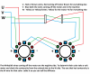
Hello all, First post but I has stumped me. In the picture in the center next to the letter A makes no sense. According to that all the wires connect together. The driver has only 3 wires u v w but the motor is a 6 wire stepper. If it had 4 wire driver I could figure it out. I can get the motor to move but it's vary choppy. Any thoughts guys?

Let me know if the picture needs to be better.
 

Attachments

  • 20161012_134752.jpg
    20161012_134752.jpg
    232 KB · Views: 101

RichardSWF

Oct 12, 2016
4
Joined
Oct 12, 2016
Messages
4
Got a better view of what the pic i was talking about
 

Attachments

  • motorWiring.png
    motorWiring.png
    102.9 KB · Views: 94

Bluejets

Oct 5, 2014
6,927
Joined
Oct 5, 2014
Messages
6,927
It's not a "point to point" wiring diagram but rather a "representation". The part you are referring to shows the wiring for x is a star connrction and below that you will see a similar arrangement for a delta connection.
 

Tha fios agaibh

Aug 11, 2014
2,252
Joined
Aug 11, 2014
Messages
2,252
Are you sure that driver is suitable for your 6 wire stepper? I would expect 4 phases and 2 common wires. It also shows two separate motors: X and Y, not one unipolar motor.
 

RichardSWF

Oct 12, 2016
4
Joined
Oct 12, 2016
Messages
4
Just figured it out. The leads going into the motors had a partial break so the motors where not getting enough amps. Also figured out how it's wired. Once I have a chance to draw it out I will post it and it will make more sense. But I will try to explain it. So I will start with V or blue as it is on the machine. Power goes in the blue through phase 1 of stepper A the "negative" of blue goes over to the other stepper through blue (phase 1) of stepper B. It's negative comes back to A and goes in W or yellow on this motor making phase 2 goes over to B through yellow and it's negative comes back to A to the U or red to make phase 3 goes over to B through red and goes to V or blue on stepper A to complete the circuit. Power is supplied in line. Then through some fancy switching of what phase is energized first it can run a 6 wire stepper with only 3. I know it changes the negative around. So at any given moment one of the leads in is positive and one is negative. For example V is + so U is now the - so make a step the driver makes W + and V - the next step is U+ and W- and it continues. I know the driver uses some fancy diodes to make this happen but yea. I'll draw it out and it should make more sense than.
O and I am a industrial sewing machine tech and this is on a 6 head 15 needle embroidery machine.
 

RichardSWF

Oct 12, 2016
4
Joined
Oct 12, 2016
Messages
4
Ok Did the wiring diagram. But I also Have a better understanding of how it does the movement. So lets start with V. When V is energized the driver will make W the negative. This will prevent the green and red coils from energizing. to make a step to the right the driver will make W the pos and U the neg, then U as the pos and V as the neg. and so on to continue motion in that direction. I think the reason that this method of driving the motion is used in Sewing machines is because they need make small steps in one directions then go back the other direction in a small step. You never need to make a long motion in one direction very fast.

Anyway Figured i would get this info out on the web because when i looked for it i could not find anything on driving a 6 wire stepper with 3 wires using a U V W driver.
 

Attachments

  • XaxisWiringTemplateColor.png
    XaxisWiringTemplateColor.png
    657 KB · Views: 75
Top