Maker Pro
Maker Pro

Monitor

Carlitos

May 25, 2017
4
Joined
May 25, 2017
Messages
4
Trying to repair monitor ctx vl710. Dont had horizontal. Transistor dont have continuity to ground (emiter). dont have resistor emiter ground, or shorcircuit emiter ground. Of course i dont have schematic. Somebodi know how is the circuit?.
Thanks,
Carlitos
 

73's de Edd

Aug 21, 2015
3,628
Joined
Aug 21, 2015
Messages
3,628
See if you find some some floating solder connections to the HOZ output tranistor.
Pass a photo of that area if possible, also including the driver transformer and its transistor that feeds the HOT along with their part numbers.

73's de Edd
 

Carlitos

May 25, 2017
4
Joined
May 25, 2017
Messages
4
Nobody is unsolded, add a leter and 3 photos.
CTX VL710_01.DSN
Comentario sobre el horizontal.​
Here is the schematic. Someone (kjr) change the circuit. The resistor, or the grounded emitter, disappear. The original was obviously changed with the visible intent of damage. If somebody has a similar good schematic, please send me. Ill transform those horizontal in something that run. Don't inspect all, but i think that must have tension control of flyback to change the definition, so cant inspirate in a TV circuit.
73s is too less, plis more. Lu2dvt
gracias
thanks
arrivederci
buenas singladuras

Sorry, those uncapacited dont allow send the photos.

In one tv circuit, pin 1 of T402 is grounded. Here, T303, in the up side is draw as a transformer, in the down side have five solders pins, three(3) of them not connected.
Thanks
Carlitos
 

Attachments

  • Fotos 024.JPG
    Fotos 024.JPG
    260.1 KB · Views: 49

Carlitos

May 25, 2017
4
Joined
May 25, 2017
Messages
4
here may be the photos
 

Attachments

  • Fotos 022.JPG
    Fotos 022.JPG
    451.1 KB · Views: 57
  • Fotos 023.JPG
    Fotos 023.JPG
    278.5 KB · Views: 58
  • Foto de circuito2.jpg
    Foto de circuito2.jpg
    38.9 KB · Views: 60
  • Fotos 024.JPG
    Fotos 024.JPG
    260.1 KB · Views: 51

davenn

Moderator
Sep 5, 2009
14,264
Joined
Sep 5, 2009
Messages
14,264
Hi Carlitos

I have labelled 4 significant dry joints

any or all of which would cause problems
I would use solder wick and suck up ALL the existing solder on those joints and then redo with new solder
I would also redo all the other joints in that area around those top 3 that are marked

tvbrd.JPG
 

73's de Edd

Aug 21, 2015
3,628
Joined
Aug 21, 2015
Messages
3,628
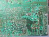
I'll buy 3 of the joints conditions, BUT with this being a single sided board and with that cluster of three connections, being on "DEAD" pads that have no involved other connections actually being made into them.

HOWEVER the right bottom connector of the three IS BEING involved, along with its terminal just to the left of it.
The two constitute one winding of that T303 transforner, of which they are using only that one winding, as being a a ringing inductor associated with a SMPS.

BUT . . . . in looking at the foil pattern that routes up to that just mentioned left terminal, he has used a marker to trace out the path up to that left terminal .
I suspect what the photo seems to show, is a like MARKING he has placed on that right terminal's solder blob . . . . . .de veras ? . . . . Carlito .

(DAVENN . . . notice the limited use and insertion of any foreign language, well down within the context . . .as your sites "bots" seem to put a hold on any post initially being STARTED in a language other than Englee . . . . .to wit . . . . . . my Russskie used on an earlier post to Richard9025. )

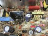
The 4th questioned connection would be the "dead" terminal on the unused #8 assignment on the flyback transformer.

BUT . . . . . those ARE being superb examples of floating terminal joints . . . . . BUT not being the REAL stealthy ones, that just rise up to develop a circular fractured ring joint , that is very hard to see.
UNLESS there is some current being carried by that connection, and the the joint starts arcing and progressively ever opening up the joint, blackening it and widening the gap to make it easier to see.

You REALLY know when you have found that condition, when you can grasp he tip of its central wire / terminal and watch it wiggle from side to side . . . . or take a fingernail to pull on and release, to tereby flick it and listen to it "ping".


73's de Edd
 
Last edited:

Carlitos

May 25, 2017
4
Joined
May 25, 2017
Messages
4
Sorry, I have "sentido del humor ácido".
Those points was desolder becouse I need to see what happens. The trafo hadn't secondary wingding, so don't need to be solder. Pads of pcb are on air. First time I try to use that monster, those was solder and it not "funca".
Whatever the problem was, emitter hadn't resistor or continuty with ground. So in this way it can't funcar.
Thanks,
73's of Carlitos
 

davenn

Moderator
Sep 5, 2009
14,264
Joined
Sep 5, 2009
Messages
14,264
Sorry, I have "sentido del humor ácido".
Those points was desolder becouse I need to see what happens. The trafo hadn't secondary wingding, so don't need to be solder. Pads of pcb are on air. First time I try to use that monster, those was solder and it not "funca".
Whatever the problem was, emitter hadn't resistor or continuty with ground. So in this way it can't funcar.

you are not being very helpful :rolleyes:
I'm outta here
 
Top