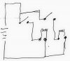
You need some kind of cross-connected latching function. With single-pole switches it cannot be done without adding some electronics. Because you have only two stations, this can be done with one chip, 4 diodes, some resistors, and output transistors. How many lights are there? You mentioned one in your original post, but there are two in the schematic.
ak