FuZZ1L0G1C
- Mar 25, 2014
- 366
- Joined
- Mar 25, 2014
- Messages
- 366
FuZZ1L0G1C submitted a new Project Log:
Low-drain Long-life audio clicker
Read more about this project log here...
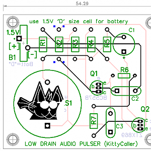
Low-drain Long-life audio clicker
Reading a post for Blind Cat's "sounder / navigation" aid, prompted me to try this relatively low-cost idea.
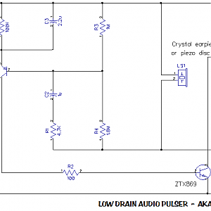
About the circuit:
Based originally on a low-drain LED blinker, the modified design replaces the hi-bright red LED with a high-impedance audio sounder.
The idea is that roughly every second, a brief pulse of around 2 V maximum is discharged to the speaker LS1, which should create a soft, audible click.
The soft tic..tic..tic will be audible to the cat, but won't drive humans up the wall.
The circuit design can drive an LED for up to 2 years, so battery should last quite long driving a high-impedance (small current) load, the speaker.
Basically the circuit trickle-charges the cap, which discharges through LED / speaker, rather than pulsing the LED / speaker directly.
For amplification and directionality, glue or mount sounder to a small dish, a flat clean tuna-can or similar.
Capacitor C1 value can be altered from 100 uF (100 micro-farads) to other for different pulse-train frequency.
Obviously, a faster pulse-rate means shorter battery life, and vise-versa.
Bill of Materials for "KittyCaller":
Resistors [all 1/8 W - 1/4 W 5% tolerance]:
1=4K7
2=100R
3=1M0
4=1M8
5=27K
7=10K
Capacitors:
C1=100u 10V electroytic radial
C2=1u ceramic disc or other NP
C3=2u2 ceramic disc or other NP
Transistors:
Q1=BC557B PNP BJT
Q2=ZTX869 NPN Axial planar (observe static precautions).
Battery:
B1=1.5V "D" size cell.
Sounder / Speaker:
LS1=Piezo-ceramic wafer-disc or high-impedance crystal earpiece.
Misc:
Double-sided Printed Circuit Board, 54mm x 46mm, designed and etched.*
Battery holder for 1.5V "D" cell.
Small plastic case to house PCB, speaker** & battery**
Flexible hookup wire for LS1 and B1.
*re PCB: If you don't have the resources / nearby outlets to have a PCB made, use strip-veroboard.
As the circuit is a fairly simple design, veroboard will suffice.
** re speaker & battery: These can optionally be outside of case.
Read more about this project log here...
