Maker Pro
Maker Pro

Klipsch ProMedia 2.1 subwoofer circuit help

GuberX

Oct 9, 2016
8
Joined
Oct 9, 2016
Messages
8
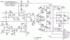
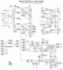
I got given a PC Subwoofer, Klipsch ProMedia 2.1, the sub is self powered, along with speaker outputs. What I planned on doing was figuring out how I can hook and 3.5mm male plug to it for use as a standalone subwoofer.

The system had a controller for volume and bass control, plus headphone jack and mic jack. I do not need bass or volume control or even the headphone or mic jack. just want to use it as a plane jane subwoofer.

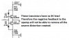
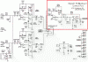
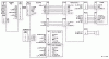
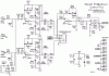
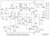
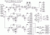
I am going to provide the schematics to the sub, I just would like a hand on where I can send the audio signal to for the subwoofer. I have attempted a few tests with no good results. I suspect I may need to do a few things to make sure volume output is full power as I will control volume level from another source. and possible make sure bass level is either max or mid as I will have separate control for subwoofer.

any help will be much appreciated.
 

Attachments

  • 2-1_interconnect2-717x399.GIF
    2-1_interconnect2-717x399.GIF
    9.4 KB · Views: 657
  • 2-1_contol-708x500.GIF
    2-1_contol-708x500.GIF
    12.6 KB · Views: 977
  • 2-1_hf_amp_712x523.GIF
    2-1_hf_amp_712x523.GIF
    12.4 KB · Views: 1,262
  • 2-1_ioboard_706x505.GIF
    2-1_ioboard_706x505.GIF
    12.2 KB · Views: 654
  • 2-1_lf_amp_708x409.GIF
    2-1_lf_amp_708x409.GIF
    11.3 KB · Views: 1,061
  • 2-1_supply-714x785.GIF
    2-1_supply-714x785.GIF
    18.8 KB · Views: 874

73's de Edd

Aug 21, 2015
3,622
Joined
Aug 21, 2015
Messages
3,622
Sir GuberX . . . . .

Why 'soitanly . . . . .

This should get her going, if its electronics is functioning, I showed the speaker interconnect but I assumeTHAT is already hardwired in the unit.

PICTORIAL REFERENCING:

Klipsh Pro Media 2.1.jpg


73's de Edd
 
Last edited by a moderator:

GuberX

Oct 9, 2016
8
Joined
Oct 9, 2016
Messages
8
okay, so I will definetly try that connection out once I replace the 2 resistors(R120 and R107) that are fried(most popular ones to fry on this unit, part of the power supply PCB)

I had tried going through the ps/2 port that the controller plugs into, but had no luck lol.
Thanks for the awesome diagram. :)
 

Audioguru

Sep 24, 2016
3,656
Joined
Sep 24, 2016
Messages
3,656
It is a strange circuit.
 

Attachments

  • Klipsch amplifier.png
    Klipsch amplifier.png
    37 KB · Views: 308

GuberX

Oct 9, 2016
8
Joined
Oct 9, 2016
Messages
8
Had the chance to test that out, was waiting on my resistors to come in to fix it. When connecting to P01 pin1 and 2 and putting some audio through it, the subwoofer sounds like its putting out full rang, not low freq only.
 

73's de Edd

Aug 21, 2015
3,622
Joined
Aug 21, 2015
Messages
3,622
Okay then, that is good to hear that you have an actual working unit .
Instead of some unit which was given to you just because it did not work.
I am now making the assumption that you do not have the units control portion .
And with my making a further analysis of the units design I am seeing that the systems
active low-frequency bypass filtering is being incorporated within THAT separate unit .

Make reference to your 2.1 – control schematic, which you supplied, and look at the very top right corner and you will see two operational amplifier sections serving as a LOW FREQUENCY pass filter for the unit, that then feeds into the sub woofer power amp.

If there is no headphone jack being plugged in, a sample of both the right and left channel are sent over to that filter section.
So, if you don't have that control section available, you will have to breadboard up that small amount of circuitry.
Such a small amount of effort , to fully take advantage of something that was given free to you.
Further info is available if you require it .

73's de Edd
 
Last edited by a moderator:

GuberX

Oct 9, 2016
8
Joined
Oct 9, 2016
Messages
8
so the LF frequency filter is in the controller?... and from what you said, as I do not have the controller, i would have to put together the section I outlined in red?

I also attached a picture of the pcb for the controller, as Im not sure if I will need the TL074 chip for this.
 

Attachments

  • 2-1_contol-708x500-edit.gif
    2-1_contol-708x500-edit.gif
    15.9 KB · Views: 326
  • cp_2-1_pic7.jpg
    cp_2-1_pic7.jpg
    62.1 KB · Views: 280

Audioguru

Sep 24, 2016
3,656
Joined
Sep 24, 2016
Messages
3,656
One TL074 has 4 opamps in it. You need the entire controller circuit, not just the parts outlined in red.
The lowpass filter must be fed from a very low impedance like from the outputs of the amplifiers shown on the left side of the lowpass filter.
 

73's de Edd

Aug 21, 2015
3,622
Joined
Aug 21, 2015
Messages
3,622
If you have that board that is shown in the picture, you are in business . . . do you ?

73's de Edd
 

GuberX

Oct 9, 2016
8
Joined
Oct 9, 2016
Messages
8
no that was a picture i found on a website based on some repairs to the Klipsch ProMedia 2.1. If i had the controller, I don't think I would have made it to this forum lol. the controller is about $70-$100CAD... so if i can build one for a lot less, i will lol.

I am looking at some opamp chips, was thinking on the OP275, as I do not need 4 channel out, left and right signal to sub is all i am looking for out of this thing.

I am trying to put together a parts list to build the controller... but since I only subwoofer out, not using speaker outs. could i use a different low frequency filter circuit? like the one i attached? Just having troubles reading the poor quality schematic of the klipsch controller. like I have no idea what is going on in sections VR501:1, VR501:2 and VR502. my knowledge in electronics is a little on the lower side, I only have taken electronics lvl 1 in school. lol
 

Attachments

  • TL072 Car Subwoofer Filter Circuit.png
    TL072 Car Subwoofer Filter Circuit.png
    55.5 KB · Views: 815
Last edited:

Audioguru

Sep 24, 2016
3,656
Joined
Sep 24, 2016
Messages
3,656
The subwoofer lowpass filter circuit you found will work but you will be missing the matching stereo highpass filters for the mids and highs speakers.
The circuit outlined in red before is a highpass filter, not a lowpass filter.
 

GuberX

Oct 9, 2016
8
Joined
Oct 9, 2016
Messages
8
thanks Audioguru, I am only wanting the low pass for the sub, I am not using the speaker outs from the sub
 

73's de Edd

Aug 21, 2015
3,622
Joined
Aug 21, 2015
Messages
3,622
.


Sir GuberX . . . . .


The schematic which you came up is being fine, since it is both taking care of the combining of the right and left channel info to get a blended R+L to feed to the low pass filter at its initial input circuitry.
Both the RED defined circuitry of the original unit and the end circuitry of this last supplied schematic are low pass filters. The front end of this new schematics also matches interfaces better into the audio supplying sources middle of the road 10 k Z input impedance commonly encountered on solid state low level audio output audio impedances,with 47 K Z being the spectrum's other end.

Even with my decades of techno expertise and long time amassed inventory of ~ 1 million parts . . .if this was being my exact situation to solve . . . I find that current day times and conditions would tend to make me just order myself one of these shown below.
The are a multitude of this same "cloned" board, being available from suppliers on Aliexpress.
One supplier even offers it with sets of SHIELDED leads and companion plugs and jacks instead of this units shown Euro terminals.

You just get your isolated and filtered supply voltage from the + terminal of electrolytic C111 of the power supply.
Then you decide if you want to mount and have the knobs protrude thru the front panel or just preset them and hard mount inside the cabinet. Then, externally control the AF incoming level.
The price is DEFINITELY right, only with a downside being the weekly-biweekly amassing of orders and then drop shipping to CONUS . . or west coast Canada . . . Vancouver ? with the units final delivery via Chinese Rickshaw Express.

URL of one of several suppliers :

https://www.aliexpress.com/item/2-1-3channel-10-24V-single-supply-overweight-bass-front-stage-board-finished-low-pass-filter/32724357927.html?spm=2114.01020208.3.1.V8VHys&ws_ab_test=searchweb0_0,searchweb201602_5_10065_10068_10069_10084_10083_10017_10080_10082_10081_10060_10061_10062_10056_10055_10054_10059_10078_10079_10073_10070_421_420_10052_10053_10050_10051,searchweb201603_9&btsid=98befd0f-e556-49e6-8ef7-5550635f0cbb

It'sa looka like-a - dis :

With mark-ups . . . . . (after I read the boards foils for the pots functions )

Preamp and LPF  fo sub woofer.jpg

73's de Edd


.
 
Last edited:

Audioguru

Sep 24, 2016
3,656
Joined
Sep 24, 2016
Messages
3,656
I repeat: The filter circuit from the Klipch manual that is outlined in red is not a lowpass, it is a highpass which is simulated here:
 

Attachments

  • highpass filter.png
    highpass filter.png
    23.7 KB · Views: 210

GuberX

Oct 9, 2016
8
Joined
Oct 9, 2016
Messages
8
wow, both you guys are awesome....

Audioguru - i see you did some work to show that the outlined schematic is highpass, which in my mind is weird due to the fact that it is labeled at the far right "SUB POD". Either way, I am not going to use the stock schematic, therefore vetoing that all together.

73's de Edd - That is a very good suggestion, but where is the fun in building the lowpass filter over buying one?... besides from AliExpress, I would see that board in over 50 days for the cheapest shipping method. Being on Vancouver Island and all... but I will defiantly consider that option if I decide to get lazy lol

I will keep you guys posted on which way I am going to go
 

Audioguru

Sep 24, 2016
3,656
Joined
Sep 24, 2016
Messages
3,656
The Chinese circuit board ad has no audio spec's and does not say which opamp is used. I wonder why their translation says it is "overweight"?
 

73's de Edd

Aug 21, 2015
3,622
Joined
Aug 21, 2015
Messages
3,622
Sires . . . . .

The unit is totally adequate for this situation and it is incorporating a low noise NE/SE 5532 I.C.
I used to use these in preamps and you really can mike up and hear a mouse a peein' on a cotton ball.

The Chinese wording is merely implying that this circuitry is accomplishing MORE than is being the norm.

Specifically . . . other units just select a knee frequency and use fixed value parts and that frequency knee is what you get.
On this one, as I mentioned in having "read" the board by looking at its foil patterns and associated components.
I see that this one is using that left control to let you "walk" the crossover knee up or down ~ 50 hertz towards the mid range.
That is why this unit is " overweight" ( being more versatile) when being compared to others, with them being fixed frequency units.


GuberX


I absolutely did not know your degree of techno-machano-electro expertise.
Like if you could draft- layout of PCB board, drill, stuff and make a board for your last supplied circuit.
For one with little PCB construction experience, along with use of an I.C. with several 0.1 in interspacings.
A Vero strip board and a ream of paper to initially plot it's cut outs and jumpers would be a simpler alternative to the make up of a full blown etched PCB.


Sir Donald . . . . .

A low-pass filter is a filter that passes signals with a frequency lower than a certain frequency knee and attenuates signals with frequencies higher than the cutoff frequency.

upload_2016-10-25_6-19-7.png

This LP filter is going to receive the R + L mixed full range signals and pass through to the SUB woofer amp all of the LOW frequencies below the knee with minimal attenuation and above the knee point all of the MID RANGE and TREBLE signals are VERY HIGHLY attenuated.
Your low BASS frequencies pass through unimpeded to the subwoofer amp.
That is the requirement.


A high-pass filter is an electronic filter that passes signals with a frequency higher than a certain frequency knee and attenuates signals with frequencies lower than the cutoff frequency

upload_2016-10-25_6-20-1.png

This HP filter is going to receive the R + L mixed full range signals and pass through to the SUB woofer amp all of the MID RANGE and TREBLE signals above the knee with minimal attenuation and below the knee point all of the BASS signals are VERY HIGHLY attenuated.
Only your MID RANGE and TREBLE frequencies get unimpeded to the subwoofer amp.


Soooooooooo of both filter circuits which we referred to previously . . . . . . which you declare to be high pass circuits . . .they would ONLY get mid range and treble signals to the LOW FREQUENCY SUB WOOFER AMP.

NO LOW FREQUENCY BASS.

A TOTAL antithesis.

From a manner of comparative semantics . . . . the filters given wording . . .is WHAT the filter DOES. e.g..

A LOW pass filter passes the LOWS and attenuates the HIGHS (and mid band).
A HIGH pass filter passes the HIGHS (and mid band) and attenuates the LOWS


73's de Edd
 
Last edited:

Audioguru

Sep 24, 2016
3,656
Joined
Sep 24, 2016
Messages
3,656
Here is the lowpass filter shown on the Klipsch I/o board. Its slope is not very steep.
 

Attachments

  • Klipsch lowpass filter.png
    Klipsch lowpass filter.png
    26.1 KB · Views: 251

73's de Edd

Aug 21, 2015
3,622
Joined
Aug 21, 2015
Messages
3,622
Sires . . . . . . .

Yeeaaaaaaaa . . . . . .

"HOUSTON . . . . . . .We have recognition and confirmation of a LOW PASS filter's presence."

However . . . you have to ignore quite a bit of that initial frequency plot due to speaker dynamics.
It does not even come into play until encompassing their assigned 30HZ low end . . . .and I
somewhat question the speaker manufacturers db down referencing at that spec.
It would seem to be a stretch at 40HZ with that speaker and enclosure used.
So you can see that the "ski slope" is encountered quite rapidly from that low freq and is even
retaining and imparting some presence of the male and female voicing in the BLUE-VIOLET range.


ReReference:

upload_2016-10-26_3-11-54.png


73's de Edd
 
Last edited by a moderator:

Audioguru

Sep 24, 2016
3,656
Joined
Sep 24, 2016
Messages
3,656
I looked up the Klipsch ProMedia 2.1 speaker system to see what it has. Tiny 3" woofers in the satellites that are supposed to play down to 48Hz! A 6.5" small "subwoofer" that cuts off its bass at 48Hz! The spec's claim response from 31Hz on up but with no dB's. I suspect that it booms at about 80Hz with no deep bass. Hey, it is a computer speaker system, not a hi-fi speaker system.
 
Top