Maker Pro
Maker Pro

I need to identify these smd's

Question

Dec 9, 2015
4
Joined
Dec 9, 2015
Messages
4
Can anyone identify these smd's? Thanks for the help in advance.
 

Attachments

  • KA1.JPG
    KA1.JPG
    68.2 KB · Views: 110
  • KA3.JPG
    KA3.JPG
    69.4 KB · Views: 113
  • VH0.JPG
    VH0.JPG
    58.7 KB · Views: 107

davenn

Moderator
Sep 5, 2009
14,260
Joined
Sep 5, 2009
Messages
14,260
Mabuhay

they are chip capacitors, the text on a couple of them may or may not refer to
either a value or manufacturer .....
buy yourself a digital capacitance meter that can go as low as 1 pF
its how I identify chip cap. values


Dave
 

73's de Edd

Aug 21, 2015
3,622
Joined
Aug 21, 2015
Messages
3,622
.


¿ Sir Question ? . . . . . . .


Pagbati. . .
kung paano ang lahat ng bagay sa iyong mga magagandang bansa ngayon. . .du Clark AFB 1960's

See . . .I haven't forgotten ALL of my "tag-a-long"

By utilizing the EIA198 numbering protocal look-up, the KA1 would be a 1000 pf unit while the KA3 would be a 10 picofarad unit . . . . . the unit with the "VHO" designation
does not fall within their valid numbering coverage. Soooooooooooo . . . . . .looks like you will have to pull out your tape measure for that one .


73's de Edd

.
 

Question

Dec 9, 2015
4
Joined
Dec 9, 2015
Messages
4
Hi, Thank you both for the help and the quick reply. That verifies the information I found right after I asked about them on this page.

http://www.marsport.org.uk/smd/mainframe.htm

The (VH0) capacitor according to that formula would be : V=Manufacturer H=2.0pf 0=0 2.0pf x 0 = 2.0pf (this was correct via lcr meter.)
Before I wrote this post I used my LCR meter on all of the smd's but was not sure if the values were correct. I assumed they were caps but I'm not an engineer so I wanted some professional feedback.

They all check out now. Thanks.

One other question though...

What is an acceptable tolerance for these? For example the KA1 on my lcr meter is 10.5pf when it is rated @ 10pf.
 

Attachments

  • Ceramic coding.JPG
    Ceramic coding.JPG
    128.2 KB · Views: 87

davenn

Moderator
Sep 5, 2009
14,260
Joined
Sep 5, 2009
Messages
14,260
What is an acceptable tolerance for these? For example the KA1 on my lcr meter is 10.5pf when it is rated @ 10pf.

That's pretty good :) they would be likely to be ± several pF
 

73's de Edd

Aug 21, 2015
3,622
Joined
Aug 21, 2015
Messages
3,622
.

Sir ? . . . . . .


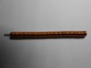
I don't know the end circuit application . . . . .like a resonating element of a tuned RF circuit ? . . . . but assurredly a silver mica cap probably would be specified for that critical of an application.
The 1000 pf value would be more in order for bypassing.

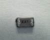
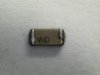
10 versus 10.5 should be fine, due to test lead capacitance if not in a dedicated holder, with the tested unit being right at the meter terminals.

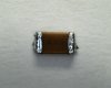
MY time derived perfect procedure, even while using test leads, is to lay down the part and probe/press test lead 1 to the first connection of the cap and then move probe test lead 2 up to
within 0.99985361cm cm of touching the caps other connection. Freeze any and all movement and mentally note the reading on the cap meter . . . .that is being all stray capacitance present.
Then make that micro move of 0.00014369cm to then connect to the caps other connection and subtract the earlier stray capacitance to get the corrected reading, it being less stray capacitance.
Of course the instrument has its own error on such very low values, but at least, a big old stray capacitance error was not being added in.


73's de Edd


.
 

Question

Dec 9, 2015
4
Joined
Dec 9, 2015
Messages
4
Hi again,
Thanks again for the help. These components are from a FM transmitter I bought in the states 20+ years ago at a gun show I believe. I attached the pictures of it with associated items, mic, 9vdc adapter and antenna. I seem to remember it working really good. You just find a FM radio station with static and find the signal by blowing into the mic and and turning the variable capacitor on the transmitter. I am attempting to define all the components to remake it using smaller package smd's to experiment on how small I can make it. The circuit seems pretty simple. I liked it, so I saved it in a tool box for a while until I got around to fooling with it again.

I have one smd item I cannot define on the board. I get readings on capacitance and inductance (measured while device removed from board). I am guessing it is an inductor. The reading I get on inductance is .2uH. I marked the undefined smd with an red arrow on the picture. Maybe someone can identify the device based on its placement in the circuit?
Thanks.
J
 

Attachments

  • Fm Transmitter.jpg
    Fm Transmitter.jpg
    92.3 KB · Views: 91
  • Microphone.JPG
    Microphone.JPG
    31 KB · Views: 67
  • 9vdc plug-adapter.jpg
    9vdc plug-adapter.jpg
    2.7 KB · Views: 82
  • Antenna.JPG
    Antenna.JPG
    52.5 KB · Views: 102

73's de Edd

Aug 21, 2015
3,622
Joined
Aug 21, 2015
Messages
3,622
.


Sir Question . . . . . . .

Assumption correct . . . .
Optimizing of ONLY the detail on the mystery device, for a closer inspection and the relationship to the 1A transistor tends to assign it as being the inductive component of the units FM L / C oscillator circuit.
The ceramic trimmer to its right, is being its variable C tuning portion.
The output FM RF then couples to the FM antenna via the " VHO" capacitor.

mRT4i81.jpg


73's de Edd

.
 
Top