Maker Pro
Maker Pro

I have issues with MAKE: Electronics experiment 8? (The link may not work so tell me

Status
Not open for further replies.

nyancatvsghosthead

Jan 7, 2012
117
Joined
Jan 7, 2012
Messages
117
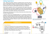
Everyday, up until yesterday, I tried repetitively to get experiment 8 of MAKE: Electronics to work. I gave up on switching the circuit myself, and am now asking for help. May I please have a solution. And if so, can I please have a picture of the circuit, in its most basic form please? Not the one in the youtube video, etc. but I mean like the original circuit? Here is a picture. Please tell me what I'm doing wrong.


Here's the link:

http://s1111.photobucket.com/albums/h476/ghostvsghosthead/
 

(*steve*)

¡sǝpodᴉʇuɐ ǝɥʇ ɹɐǝɥd
Moderator
Jan 21, 2010
25,510
Joined
Jan 21, 2010
Messages
25,510
They flash up the circuit diagram on the video.

Probably best not to listen to the explanations too closely though, they're a bit suspect (if well intentioned)
 

Laplace

Apr 4, 2010
1,252
Joined
Apr 4, 2010
Messages
1,252
Just what is it that doesn't work. The relay is wired as a vibrator; when you press the switch it is supposed to vibrate. Does it not vibrate? Can you not find the switch? Do the LED's not light up? Did it work before you added the capacitor? How about if you removed the LED's, the resistor, and the capacitor; does the relay vibrate then? Don't add any other components until the vibrator works.
 

Attachments

  • Experiment8.png
    Experiment8.png
    73 KB · Views: 443

nyancatvsghosthead

Jan 7, 2012
117
Joined
Jan 7, 2012
Messages
117
I'm sorry to ask such a stupid question but when you say "the relay is wired to the vibrator" do you mean that as in "You did it perfectly" or "that's the only part you did wrong?" because I tried replacing the LEDs though I COULD replace them again, and I KNOW that the relay will work regardless of whether or not it has its skin taken off like in that earlier experiment right? That I know. I don't know how I could possibly do this completely wrong in such a way, but I did obviously so...
 

Laplace

Apr 4, 2010
1,252
Joined
Apr 4, 2010
Messages
1,252
The instructions for the experiment state, "...and then press the pushbutton very briefly. You should hear the relay make a buzzing sound."

So did you hear the buzzing sound?
 

Attachments

  • Experiment8b.jpg
    Experiment8b.jpg
    106.1 KB · Views: 434

nyancatvsghosthead

Jan 7, 2012
117
Joined
Jan 7, 2012
Messages
117
Do I need to flip it over? Should it be perpendicular to where it is or something. I tried flipping sides but I COULD try flipping it within the side it's on if anyone thinks that that will work. Thank you so much for the help. I'm just asking this b/c I think that it may make some sense. If so, could I have a diagram of how to do it that way, or a picture of it being done? I seriously think something is going wrong. Maybe I should have bought a different electrolytic capacitor, I mean the same one but a second time. Are any of these good ideas? I would like another suggestion because the press it briefly idea didn't work but thank you for the try though. I admire your effort to answer my question.
 

(*steve*)

¡sǝpodᴉʇuɐ ǝɥʇ ɹɐǝɥd
Moderator
Jan 21, 2010
25,510
Joined
Jan 21, 2010
Messages
25,510
From Laplace's diagram, you need to initially connect up the wires shown in red and blue.

You do need to ensure that the pinout of your relay is the same as in the example, it may not be.

When you press the button, one of 4 things may happen:

1) nothing
2) you hear a click
3) you hear a buzz
4) smoke and flames erupt

The first 2 indicate a wiring error, the second is good, the third indicates you have made a wiring error *and* you need to replace something.

The orientation should not matter.

If you are still stuck, tell us everything that is written on the relay and we will try to find the specs and tell you exactly where to connect the wires.
 

nyancatvsghosthead

Jan 7, 2012
117
Joined
Jan 7, 2012
Messages
117
Do the wires, connected to negative and positive, need to be on the same side as the rest of the circuit or the opposite side.
 

(*steve*)

¡sǝpodᴉʇuɐ ǝɥʇ ɹɐǝɥd
Moderator
Jan 21, 2010
25,510
Joined
Jan 21, 2010
Messages
25,510
I don't know what you mean by "same side [...] or the opposite side"

They just have to be connected to the right places and not connected to anything wrong
 

nyancatvsghosthead

Jan 7, 2012
117
Joined
Jan 7, 2012
Messages
117
I meant, if the circuit is closer to the left side of the breadboard, but the wires, connecting it to the adapter, are on the right (measuring the side with more length from left to right), does that matter at all?
 

(*steve*)

¡sǝpodᴉʇuɐ ǝɥʇ ɹɐǝɥd
Moderator
Jan 21, 2010
25,510
Joined
Jan 21, 2010
Messages
25,510
No.

In this application it may be an issue if some of the wires were tens of metres longer (and purely because they would have enough resistance to affect operation).

A few cm (or even a metre) isn't going to have any significant effect in this circuit.
 

nyancatvsghosthead

Jan 7, 2012
117
Joined
Jan 7, 2012
Messages
117
It says NTE Electronics Inc. It also says this:

A25-11D10-12
10A 277 VAC
10A 20 VDC

So is there anything wrong with the relay?
 

(*steve*)

¡sǝpodᴉʇuɐ ǝɥʇ ɹɐǝɥd
Moderator
Jan 21, 2010
25,510
Joined
Jan 21, 2010
Messages
25,510
That would be an R25-11D10-12 :)

The datasheet is here.

If you connect 12V to the 2 leads that are apart from the rest, you should hear the relay pull in.

Do you?

If that's OK, then wire it up just like in Laplace's diagrams on page 1 of this thread. Just wire up the red and blue wires, the switch and the relay.

When you press the button you should hear a buzzing. Do you?
 

nyancatvsghosthead

Jan 7, 2012
117
Joined
Jan 7, 2012
Messages
117
Do you mean like this?

http://s1111.photobucket.com/albums.../?action=view&current=IMG_20120115_191636.jpg

I think you mean hook it up like that. If not, do you mean like literally, like w/o the breadboard, like just hook the button up to the relay? If not either, could you draw me a diagram of what you want me to do? What am I doing wrong? Thank you very much sir. It would be awfully nice if you answered sooner. Thank you. =)
 

Laplace

Apr 4, 2010
1,252
Joined
Apr 4, 2010
Messages
1,252
I can't tell for sure from the photo, but it appears that on the bottom the power is connected to the RED rail and the circuit is connected to the RED rail, while on the top the power is connected to the BLUE rail and the circuit is connected to the RED rail. If that is in fact the case then the circuit is not receiving any power. One of the symptoms of such a condition is that the project does not work.
 

(*steve*)

¡sǝpodᴉʇuɐ ǝɥʇ ɹɐǝɥd
Moderator
Jan 21, 2010
25,510
Joined
Jan 21, 2010
Messages
25,510
Looking at that image, the only thing I can say is that you have no connection between the relay and your power source.

You also have another component there (a capacitor?) which you don't need at the moment.

Even if you did have a connection from the power supply rails (which are presumably connected to those wires on the right of the image) to the relay, I can't actually tell where the leads come out so I couldn't tell if they were in the right place.

Yes, simply get your power supply wires and touch them to the 2 pins on the relay that are apart from the others.

You should hear a satisfying *CLICK* which is the relay pulling in. You will hear a similar (perhaps slightly softer) *click* when you disconnect the wires and the relay drops out.

Let's see if you can get that far.

The next step is to do the same thing on the breadboard. You do know how the conductors line up on these, right?

I'm replying as fast as I can. I can't do "sooner"

edit: I only looked at the *first* image. The second one can not be relevant because I suggested you *only* wire up the relay, the switch, and the power source -- oh, is that small thing a switch?
 
Last edited:
Status
Not open for further replies.
Top