Maker Pro
Maker Pro

How to Step up Voltage? DC to DC converter or Op Amp

Ian Hunter

Nov 26, 2014
4
Joined
Nov 26, 2014
Messages
4
Hi everyone,

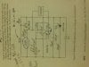
I have a circuit with a photoresitor in it (and an OP amp) that gives out a voltage range of 0-.135V.

Is there anyway I can expand the range of the voltage from 0-.135V to 0-5V to get a more dramatic change in voltage when light hits the photoresistor?
 

Attachments

  • schematic_gas.JPG
    schematic_gas.JPG
    171 KB · Views: 355

ADRT

Nov 25, 2014
192
Joined
Nov 25, 2014
Messages
192
These are easy to build with readily found components. Op amp certainly not a bad idea either.
 

Frenoy Osburn

Nov 20, 2014
64
Joined
Nov 20, 2014
Messages
64
I don't think it would be efficient to do so. He already has a 741. If he can change a few things (supply voltage) he can get it working with the existing components.

I'm waiting for @KrisBlueNZ to get to this as I can't find a good circuit for the OP. He may actually already have one.

OP: One more thing, do you want a discrete digital signal i.e 0V and then 5V? or do you want an analog signal ranging from 0-5V depending on the amount of light on the photo-resistor?
 

Ian Hunter

Nov 26, 2014
4
Joined
Nov 26, 2014
Messages
4
I would line an analog signal ranging from 0-5V depending on the amount of light on the photo-resistor. I'm using the NTE941M op amp. What do I have to change to create an analog signal ranging from 0-5V based on the schematic I provided?
 

KrisBlueNZ

Sadly passed away in 2015
Nov 28, 2011
8,393
Joined
Nov 28, 2011
Messages
8,393
Try a voltage doublet circuit or tripler. Here's a good link. http://www.coolcircuit.com/circuit/voltage/
No, don't do that. A voltage doubler or tripler is not the right kind of circuit at all!

You just need to increase the gain of the op-amp stage.

If you just want a DC voltage that increases when more light falls on the LDR, you don't need much:

271517.001.GIF
VR1 should be a multi-turn preset potentiometer aka "trimpot" such as one from the Bourns 3296W series. There's a suitable 100k one at http://www.digikey.com/product-detail/en/3296W-1-104LF/3296W-104LF-ND/1088046 but they're available from various places.

If you don't get enough voltage at the brightness level you're interested in, use a higher resistance for VR1. If VR1 is close to fully anticlockwise, use a lower resistance for VR1.

That circuit has a high output impedance. It will drive a multimeter fine, but anything else may need a buffer. If you tell us more about your project we can give you more detailed advice.
 

Ian Hunter

Nov 26, 2014
4
Joined
Nov 26, 2014
Messages
4
schematic_gas.JPG

On the schematic here, where is VR1 on this Op AMP Diagram? So I can know where to place the Bourns 3296W trimpot.

The goal of my project is to use a fiber optic cable that can take in different spectrums of light and run it into a photo-resistor to provide (Through the diagram) a range of 0-5V to read on my Arduino Microcontroller. From there I will program a plotting algorithm that will graph the change in voltages in order to see what color changes in light cause different changes in voltage. That's about it for the project.
 

Attachments

  • schematic_gas.JPG
    schematic_gas.JPG
    171 KB · Views: 205

BobK

Jan 5, 2010
7,682
Joined
Jan 5, 2010
Messages
7,682
A 741 is a terrible op amp to use with a single 9V supply. Its output voltage range will be from about 2 to 7V.

Use Kris's circuit and add a rail-to-rail single supply opamp as a voltage follower.

Bob
 

KrisBlueNZ

Sadly passed away in 2015
Nov 28, 2011
8,393
Joined
Nov 28, 2011
Messages
8,393
OK, that circuit isn't suitable for driving an Arduino input. Here's a circuit that is.

271517.001.GIF

I've used a dual op-amp, the LM358, even though only one half is used. This is your most easily available option. You can't use a 741 here as BobK said because it's not a single-supply op-amp.

The op-amp is a simple buffer or voltage follower. R1, D1 and D2 clamp the voltage to slightly over 5V to prevent damage to the ADC in the Arduino. R2 loads the op-amp output to ensure it can get all the way down to 0V. C1 is a decoupling capacitor, needed to ensure reliable operation of U1, and should be connected as closely and directly as possible between pins 8 and 4 of the device.

The supply rail needs to be at least 8V for this circuit because the op-amp can't pull its output closer than a few volts below its positive supply. Modern op-amps can do a lot better, and if you use a "RRIO" (rail-to-rail input and output) op-amp, and you don't need the top and bottom few percent of the ADC range, you can power the circuit from 5V instead of 9V.

If you tell us even more about your project we can give more advice.
 

Ian Hunter

Nov 26, 2014
4
Joined
Nov 26, 2014
Messages
4
Hi KrisBlueNZ,

With the LDR Buffer build above, it will provide a range of 0V to 5V range of output to the Arduino?

Also what does CW and CCW stand for? Is it continuous Wave?
 

KrisBlueNZ

Sadly passed away in 2015
Nov 28, 2011
8,393
Joined
Nov 28, 2011
Messages
8,393
With the LDR Buffer build above, it will provide a range of 0V to 5V range of output to the Arduino?
Yes, as shown, if you have a 9V supply.

If you want to avoid the 9V supply, you can get most of the 0~5V range but you'll need to use a different op-amp.
Also what does CW and CCW stand for? Is it continuous Wave?
Clockwise and counter-clockwise directions for the preset potentiometer (trimpot). So that turning it clockwise will increase the sensitivity.
 
Top