Maker Pro
Maker Pro

Help! Repairing water damaged PCB from Massage chair.

Jonawald

Dec 16, 2015
201
Joined
Dec 16, 2015
Messages
201
Hi there. Hope you can help.

I just made an account here to get help on a present challenge I am working on and hope to stay on for future projects I may want to tackle.

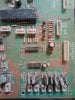
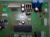
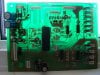
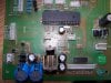
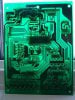
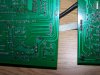
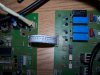
My question is this. I got a hold of some very nice full body massage chair. It was in a show room which got flooded by a few inches of water. The chairs were left standing on a shelf for years after this. The PCBs were on a shelf an inch off the floor so the only real damage to these chairs was in the electronics. I have already repaired two of these chairs. One needed a good cleaning and a replacement fuse. The second needed a bunch of resisters, diodes and caps replaced because their leads had corroded right off.

The third is where I'm stuck. I have done a lot of learning through this project and I love learning and working this out.

So far, I have replaced all the resistors, capacitors, voltage regulators, diodes etc with the same value or as close as I could manage between ordering stuff from digikey and scavenging from a heap of other boards I have around.

Problem is this. The remote does not light up when I hit power on it. I followed the circuit and found two possible reasons.

1: The power supply voltage coming in is 12V AC. (multi meter reads 13.5) After the diodes and Cap it the multi meter reads 17 VDC. I should probably state here that the 25V 2200uf cap here was replaced with a 50V 1000uf. I am not sure why there are 17V here. Maybe there is a good explanation for that. That's why I am asking.

2: The remote has four leads. VCC, RT TX and GND in that order. When I check with my multi meter, I get -17VDC at both the VCC and GND. That confuses me. I was not expecting that. I checked all the diodes they are pointing in the right direction, and I suspect that there would be a fuse blown or something if this was not as it is supposed to be.

Can somebody tell me if either of these two is the problem with this board or is there something else I need to check. The boards are all neatly labeled with the part number of the components so there was very little guess work.

Your turn. Ask questions. I can post pictures if they would be helpful ... Don't know that's why I'm here.

Jonathan
 

Sadlercomfort

Ash
Feb 9, 2013
424
Joined
Feb 9, 2013
Messages
424
The capacitor should really be replaced with a 25V 2200uF or higher voltage. The 2200uF is important.

Please show us some pictures and any circuit diagrams if you have them.

I would of thought that the remote would be 5V, but not sure at this stage. What type of remote is it?
 

Martaine2005

May 12, 2015
4,951
Joined
May 12, 2015
Messages
4,951
Hi jonawald,
As explained above, the capacitor should be replaced with the same μF rating but the voltage can be higher and not lower..
Your power supply is probably about 2Amps. As a rule of thumb, 1000μF for every Amp.

The AC input of 12V when rectified to DC will change the voltage seen too. 12VAC is an average or RMS, while the DC is showing peak. So 12V * 1.414 = 16.968.. 17 volts...

I see you have done a good job of repairing the others!
Any reason you cannot try the remote on a working chair to eliminate or verify it's working?

Does the remote VCC and GND show - (negative) 17V both ways while probed?
Can you upload pictures of the board? Nice and clear and close up?

Martin
 

Jonawald

Dec 16, 2015
201
Joined
Dec 16, 2015
Messages
201
Ok. Thanks for the reply. I will try to answer your questions best I can. First of all, I cannot put this board into the other chairs because they are all different. They were in a showroom in a line from least expensive to most expensive. So they have increasingly more complex circuits. The great learner project. The one I am doing now is the second most complex chair in the bunch.

Yes the remote VCC and GND snow -17V I do not need to move the red probe from the circuit and can move between VCC and GND without the - showing up. The voltage differs slightly though. 16.85 and 17.2. This leads me to think it must be coming in from a different direction in the circuit. I don't have a drawing, but I did take pictures of the board in question front and back.

There are three other boards to this chair, but I am trying to keep it simple by dealing with one circuit at a time here. I feel the remote is a good starting point. I also will attach a picture of the remote.

I will order a replacement cap. Thanks for the info on sizing caps. Is it OK if I leave this one in for now as I troubleshoot the board? or will it throw things off too much?

There is a transistor missing in the corner by CN27, the vibrator turned on as soon as I powered up the chair so I took that out for troubleshooting later. Don't think it's connected with remote. IMG_20151216_162320425_HDR[1].jpg
 

Attachments

  • IMG_20151216_162432154_HDR[1].jpg
    IMG_20151216_162432154_HDR[1].jpg
    218.6 KB · Views: 209
  • IMG_20151216_162439168_HDR[1].jpg
    IMG_20151216_162439168_HDR[1].jpg
    208.5 KB · Views: 160
  • IMG_20151216_162300248_HDR[1].jpg
    IMG_20151216_162300248_HDR[1].jpg
    260.4 KB · Views: 172

Martaine2005

May 12, 2015
4,951
Joined
May 12, 2015
Messages
4,951
Yes the remote VCC and GND snow -17V I do not need to move the red probe from the circuit and can move between VCC and GND without the - showing up. The voltage differs slightly though.
Sorry Jonathan,
That makes no sense to me!..

The cap you replaced wont filter enough ripple and could cause oscillations. Which wont help diagnose this..
I would suggest starting with the power supply, not the remote. The tx and rx can be bridged to simulate the remote..
The remote is just a switch on a long wire! It still goes back to the main board.

Martin
 

Jonawald

Dec 16, 2015
201
Joined
Dec 16, 2015
Messages
201
Ok then. I will do that. Will see how I can get a cap. Closest place is Winnipeg, an hours drive away. Don't get there very often. I'll try to get somebody pick one up.

Caps can be wired in parallel right? The board asks for a 2200uf/25V cap. I have two new 1000uf/25V caps here. To get me going on the next step of troubleshooting. Could I hook up these in parallel while I wait to get a proper replacement cap? I know I am still 200uf short. I have a lot of smaller caps on hand 470/25V?

Or am I just better off waiting? I'm eager to continue working on this while I have the time and inclination.

Jonathan
 

Jonawald

Dec 16, 2015
201
Joined
Dec 16, 2015
Messages
201
Here are some pictures of what I started out with.
 

Attachments

  • IMG_20151115_120451900[1].jpg
    IMG_20151115_120451900[1].jpg
    234.5 KB · Views: 156
  • IMG_20151115_120444544[1].jpg
    IMG_20151115_120444544[1].jpg
    234.2 KB · Views: 145
  • IMG_20151115_120437294[1].jpg
    IMG_20151115_120437294[1].jpg
    188.1 KB · Views: 156
  • IMG_20151115_120500310.jpg
    IMG_20151115_120500310.jpg
    275.5 KB · Views: 145

Jonawald

Dec 16, 2015
201
Joined
Dec 16, 2015
Messages
201
Ok some quick research and re-reading your post on ampsx2 to get uf. I decided that the two 1000uf/25V in parallel should cover my needs. I put them together and soldered them in. Same deal with -16.68 for GND and 15.93 for VCC. These are numbers from the multi meter not from memory as before if there is a discrepancy.
 

Jonawald

Dec 16, 2015
201
Joined
Dec 16, 2015
Messages
201
Thanks to a comment up-thread, saying that the remote should probably have 5v I isolated the problem here. there are two voltage regulators on the board. One is a 12V the other a 5v. When I checked with my multi meter the voltage was the same on pin 1 and 3. So I pulled it and retested it. I put the +12 from a power supply to pin 1, ground to pin 2 and tested the output with my multi meter. It read 5.2V. That looked good to me so I stuck it back in then re-tested. Now it read 5.2 V in the board. First thing I noticed was that the back light on the remote went on when I powered it up. Now I am at the point where I can get the actuators on the chair moving and the programs start to run on the remote. Looks pretty hopeful.

I know I am not at the end of the road of fixing this chair. None of the wires coming from the chair to the board are labeled. there are around 30. I need to check which goes where and check each one for problems. There are heaters, vibrators, solenoid... I also for sure know that some of the bigger transistors need to be replaced yet too. The good news is I have a starting point and a direction in which to head off on from here.

Thanks.
Jonathan
 

Jonawald

Dec 16, 2015
201
Joined
Dec 16, 2015
Messages
201
So after a few power cycles testing different parts, I am back to square on. -16V pm pin 3 when tested in the board. Are these L7805 regulators known to be intermittent? What's going on here?

Jonathan
 

Martaine2005

May 12, 2015
4,951
Joined
May 12, 2015
Messages
4,951
Hi Jonathan,
Yes, you can have capacitors in parallel to double the capacitance.
Glad you found that out! Opposite to resistors of course..
The LM7805 as you now know is a 5v regulator. And no, not intermittent.
Depending on other circuitry, it may be shutting down due to over voltage or cannot stay on due to lack of voltage..
I will read your updates and see if something jumps out!

Martin
 

Jonawald

Dec 16, 2015
201
Joined
Dec 16, 2015
Messages
201
In the mean time. i thought I would take some better pictures of the area of the board we are concerned with right now. The smaller of the two heat sinks is for the 5v regulator.
 

Attachments

  • 102_0500.JPG
    102_0500.JPG
    326 KB · Views: 129
  • 102_0498.JPG
    102_0498.JPG
    271.7 KB · Views: 157
  • 102_0499.JPG
    102_0499.JPG
    320.4 KB · Views: 122

Jonawald

Dec 16, 2015
201
Joined
Dec 16, 2015
Messages
201
picture of the back of the board
 

Attachments

  • 102_0501.JPG
    102_0501.JPG
    302.4 KB · Views: 129

Jonawald

Dec 16, 2015
201
Joined
Dec 16, 2015
Messages
201
Is it possible that one of the 4 capacitors crossing between the ground and that 5v rail is shorted out?
 

Jonawald

Dec 16, 2015
201
Joined
Dec 16, 2015
Messages
201
So because it is boring waiting for people to reply to this thread I went ahead and replaced all caps in the line of fire from the AC input right to the big microchip. No change. ... correction. Now instead of reading 16V it VCC reads 11V GND still reads 16V.

Something moved, but I cannot figure out what. I replaced three small 104 bright yellow caps with bright blue 104k caps from a computer power supply. I trust that these are for this intent and purpose the same caps. The others were all replaced with 35V caps of the same capacitance. the original were 16V
 
Last edited:

Jonawald

Dec 16, 2015
201
Joined
Dec 16, 2015
Messages
201
And ... Found it. I replaced one more 104 cap in that power supply area. Of the four 104 caps I replaced three had one lead rusted clean off. Now go try and troubleshoot that from pictures will you? Sorry guys, I'm having fun learning here anyway. Looks like I will need to go over this board with a fine tooth comb and replace all caps and take out connectors to check for rotted posts. I have found a few connectors already with posts rusted through between the bottom of the connector and the solder on the other side of the pcb.
 

Jonawald

Dec 16, 2015
201
Joined
Dec 16, 2015
Messages
201
Now I went off to research on the difference between a 104 and a 104k and see that there is a difference in order of magnitude. What do I do about that? Capacitors are one thing I need to do a lot more learning about. Should I leave the 104k caps I put in place of bad 104 caps or are they ok for that purpose? I have about 5 more 104s to replace. I have a lot of 104k caps but no 104.
 

Martaine2005

May 12, 2015
4,951
Joined
May 12, 2015
Messages
4,951
Sorry for the delay in replying.
Your pictures show many legs of componets that have rust.
I think it would be advantageous to remove them all, clean the leads and pcb, then check the components out of circuit before re-assembly.
You could of course just flux the whole board and re-solder each joint. But you may end up at square one again.

Martin
 

Jonawald

Dec 16, 2015
201
Joined
Dec 16, 2015
Messages
201
I have been seriously thinking about taking off every component on this board cleaning it up and re-soldering it. The only thing holding me up is all the stuff I have already taken off and re-done. I do have one of those fancy Molten Lead bath thingamajigs now. Somebody gave me one last week. I could float the board on molten lead, pick everything off and then go nuts testing everything and putting it back together again. I am so close to getting everything working though, I am still holding out. I was down to two circuits not working yesterday. I would like to try getting it going for a bit yet before I back up and start again.

I ran into trouble though and need advice. Here's my problem. Can somebody advise me or ask a question that will lead me in the right direction.

There are four relays two for back up/down two for leg up/down. This worked fine till yesterday. There was a problem with one side having a lot fewer volts than the other on the output side. 170V and 60V. Neither number make sense to me because this should be a 120V circuit. Somebody may be able to explain this.

I was going in to take out all the diodes with my soldering tool to test them and there was a bad arc from my tool to the board. Somebody had forgotten to turn off the power to the board.Some of the traces melted and there was a blown fuse. I patched up the traces and replaced the fuse.

Now the relays don't work any more with the remote. Three of them work when use the ohm meter to connect +12v to the base of the transistors. The fourth does not even though I have changed out the relay (30V coil instead of 12V coil might make that difference).

When I put my volt meter to +12V and then to the base of the transistor, I see that there is 16.7V. This does not make sense to me.

The base of the transistor that controls the non-working relay shows 14.4V.

The traces leading to these transistors come directly from the large micro controller.

What are the chances that I fried the controller?
 

Attachments

  • 102_0508.JPG
    102_0508.JPG
    350 KB · Views: 131
  • 102_0506.JPG
    102_0506.JPG
    279.9 KB · Views: 162
Top