Maker Pro
Maker Pro

GPS NMEA, Failover Circuit upgrade attempt.

chopnhack

Apr 28, 2014
1,576
Joined
Apr 28, 2014
Messages
1,576
Yes that is right. Just like on my post #242. What can i say other that chances are i am not going to use it on the circuit after all.

Are there any other direct replacements or will you have to redesign the board?
 

CDRIVE

Hauling 10' pipe on a Trek Shift3
May 8, 2012
4,960
Joined
May 8, 2012
Messages
4,960
You don't need one when only receiving data to a Picaxe. However if you need to transmit RS232 level data you may want to check these Intersil chips..

Chris
 

Attachments

  • ICL3232.pdf
    654.9 KB · Views: 79

CDRIVE

Hauling 10' pipe on a Trek Shift3
May 8, 2012
4,960
Joined
May 8, 2012
Messages
4,960
I forgot to mention this but before abandoning the MAX chips make sure you have all unused inputs tied low or high as per manufacturer's spec. Or have you already done that and I've simply forgotten? ... It is a very long thread.

Chris
 

HellasTechn

Apr 14, 2013
1,579
Joined
Apr 14, 2013
Messages
1,579
Are there any other direct replacements or will you have to redesign the board?
I am not sure about that John.
You don't need one when only receiving data to a Picaxe. However if you need to transmit RS232 level data you may want to check these Intersil chips..
Chris
So far only receive i need but thanks anyway.
I forgot to mention this but before abandoning the MAX chips make sure you have all unused inputs tied low or high as per manufacturer's spec. Or have you already done that and I've simply forgotten?
No that i have not done. Only unused picaxe pins are pulled down. Could that be the reason ? O.K. here we go testing again :)

P.S.
What resistor values should i use as pull donw for the TTL inputs of the MAX ?
 

HellasTechn

Apr 14, 2013
1,579
Joined
Apr 14, 2013
Messages
1,579
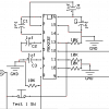
After thinking about your reccomendation, Cris, i came up with this diagram.

The difference with the old one is that i have tied pins 10 and 11 (TTL inputs) to Ground each through a 10K resistor. The same i did with Pins 9 and 13 (RS232 inputs) for when they are not connected.

I assume that for pins 9 and 13 the 10K pulldown should not cause trouble when RS232 inputs are connected. Just like with the Picaxe and the 22k and 10k resistor array.

I will breadboard and test it.

I am going to build a new "universal" PCB for this project that will be able to accept both a MAX3232 chip and the simple resistor array by removing and adding the desired components on component mounts. This will enable me to use any of theese two input methods on the same PCB simply and easily.
 

Attachments

  • new max.png
    new max.png
    29.9 KB · Views: 82

chopnhack

Apr 28, 2014
1,576
Joined
Apr 28, 2014
Messages
1,576
Did you intend to leave your two transmit pins open? Pins 7 & 14 don't show connection to anything in your diagram.
 

HellasTechn

Apr 14, 2013
1,579
Joined
Apr 14, 2013
Messages
1,579
Yes because there is no space on the PCB. I think that transmit pins dont need to be pulled down.
 

chopnhack

Apr 28, 2014
1,576
Joined
Apr 28, 2014
Messages
1,576
Yes because there is no space on the PCB. I think that transmit pins dont need to be pulled down.
If you are getting tight on space, two suggestions:1. With your through hole resistors, go vertical, or 1. Consider a surface mount resistor chip - they are small and easy enough to work with at 0805 or higher sizes. 0603 might be challenging the first go around.
 

HellasTechn

Apr 14, 2013
1,579
Joined
Apr 14, 2013
Messages
1,579
I have already fitted four 0402 smd resistors under the max3232 ! I may be able to fit two more though. It is just that signal lines are in the way. I am sure i will find some space for two more.
 

chopnhack

Apr 28, 2014
1,576
Joined
Apr 28, 2014
Messages
1,576
I have already fitted four 0402 smd resistors under the max3232 ! I may be able to fit two more though. It is just that signal lines are in the way. I am sure i will find some space for two more.
Ah! You have already used that trick!! Can you take a picture of the copper side of the board? I have the last picture from the other thread: PCB building
 

HellasTechn

Apr 14, 2013
1,579
Joined
Apr 14, 2013
Messages
1,579
Well i haven't made it yet. It should be ready by tuesday though. I am still thinking what improvements i can make based on the first PCB.
 

chopnhack

Apr 28, 2014
1,576
Joined
Apr 28, 2014
Messages
1,576
Well i haven't made it yet. It should be ready by tuesday though. I am still thinking what improvements i can make based on the first PCB.
If you are getting tight on space, consider using a pad on the copper side by the pin and solder a jumper wire to a remote location that has ground plane.
 

HellasTechn

Apr 14, 2013
1,579
Joined
Apr 14, 2013
Messages
1,579
I think i found a solution that works.
So far i had no falures with this design.

10K pulldown resistors to all unused inputs and outputs and a 20 Ohm resistor in series with the supply rail feeding pin 16.
 

Attachments

  • max.png
    max.png
    18.9 KB · Views: 76

CDRIVE

Hauling 10' pipe on a Trek Shift3
May 8, 2012
4,960
Joined
May 8, 2012
Messages
4,960
Good to hear. Now all you need to do is start using a decent schematic editor that puts junction dots where they belong. :rolleyes: I recommend free LT Spice or Tina-TI. ;)

Chris
 

CDRIVE

Hauling 10' pipe on a Trek Shift3
May 8, 2012
4,960
Joined
May 8, 2012
Messages
4,960
LT Spice IV. Also check out Tina-TI at the Texas Instruments website,

Chris
 

HellasTechn

Apr 14, 2013
1,579
Joined
Apr 14, 2013
Messages
1,579
I think i found a solution that works.
So far i had no falures with this design.

10K pulldown resistors to all unused inputs and outputs and a 20 Ohm resistor in series with the supply rail feeding pin 16.

After running the device for several hours under various conditions (GPS's connected,disconnected etc) i can confirm that the MAX3232EPE works fine when wired as described above.

LT Spice IV. Also check out Tina-TI at the Texas Instruments website,
Chris

I have tried useing them but i get confused :( . ExpressSCH is so, so easy to use.
 

CDRIVE

Hauling 10' pipe on a Trek Shift3
May 8, 2012
4,960
Joined
May 8, 2012
Messages
4,960
Actually, I find Tina very easy to use. It's schematic editor is superior to others I've used. Tina's component symbols aren't overly large and clunky, which I don't like about LTSpice.

Oh, happy to read that the pull-down resistors stabilized the RS232!

Chris
 

HellasTechn

Apr 14, 2013
1,579
Joined
Apr 14, 2013
Messages
1,579
I think i found a solution that works.
So far i had no falures with this design.

10K pulldown resistors to all unused inputs and outputs and a 20 Ohm resistor in series with the supply rail feeding pin 16.

Instead of using a standard fuse i think it will be better to use this ceramic self resettable fuses:
http://www.ebay.com/itm/112181738896?ul_noapp=true

I have read their datasheet and it says that they have an 80 ohm resistance so i guess i will have to remove that 20 ohm resistor i have put in series with the fuse. I am not sure The Max3232 will be able to work with that kind of fuse but is it worth the try.
 

Sadlercomfort

Ash
Feb 9, 2013
424
Joined
Feb 9, 2013
Messages
424
I've used these kinds of fuses before, to protect a large CPU PCB for a stairlift and other things. They're very useful as they allow you to perform maintenence on the board without changing the fuse. If you haven't fixed the fault at least you don't waste fuses.

They break the circuit very quickly in the event of a short circuit.
 
Top