What do you have coming into the box? Power has to come in on one wire and leave on another, the names may be different, but physics are the same. I thought UK has red (live) and green/yellow earth as well as a blue neutral?
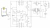
What I was going to mention was a small transformer and rectifier setup if you had the space
")