Maker Pro
Maker Pro

Geiger pulse detection circuit

sebswed

Jun 2, 2013
26
Joined
Jun 2, 2013
Messages
26
Hi all.

I'm building a Geiger counter and I have the HV part working, generating 400VDC but I'm having trouble with the pulse detection circuit. I know the tube is working because I pulled it out of a working geiger kit (I just like to see if I can build my own).

So I have a working tube, I have the HV part working, it's just the pulse detection that puzzles me...
I found a circuit online that looked very simple (attached). It uses 2x 2N5551. Unfortunately I don't have these laying around so I tried with 2x 2N4403 instead. I think I connected everything correctly but I'm not sure as it doesn't detect a pulse.

Could someone check if I connected something wrong.
All help is appreciated! :)

I have attached:
  1. HV generator schematic (works)
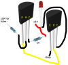
  2. Picture of my geiger counter
  3. Pulse detection circuit I found online
  4. Pulse detection circuit as it is connected
Thanks in advance! :)
 

Attachments

  • detectionSchematics.png
    detectionSchematics.png
    72.9 KB · Views: 95
  • Schematic_20170515_145229.jpg
    Schematic_20170515_145229.jpg
    34.5 KB · Views: 106
  • IMG_20170518_065753.jpg
    IMG_20170518_065753.jpg
    235.5 KB · Views: 110
  • detectionCircuit.png
    detectionCircuit.png
    74.5 KB · Views: 89

73's de Edd

Aug 21, 2015
3,622
Joined
Aug 21, 2015
Messages
3,622
Sir sebswed . . . . .

Assuming that you are properly getting the 400 VDC Geiger supply voltage by your circuitry and that it only requires a mere 1.6 VDC of power supply.

The first error noted is the use of PNP transistors in the amp circuit . . .if you have the companion family brothers to your units . . .use those 2N4400 or 2N4401 NPN units.

Also include the denoted speaker as it takes quite a strong spike to drive that LED, whereas, just a feeble sound from the speaker would be noticed by just random incidental radiation pickup.


Once you get the proper NPN transistors installed, do an initial power up with only the +5 to the transistors, and there being NO 400V power supplied to the Geiger supply.

That then lets you put a spittle wetted fingertip to the B-C leads of the left transistor of that quasi-Darlington pair of transistors, to see if there is a response by some degree of lighting of the LED.

If, not suspect that you might have its leads installed backwards. After the LED is lighting you might further test the combined amplification of the unit by STILL having NO Geiger power.


Where, you touch the wire lead of the 10 meg resistor that connects to the left transistors base, with a spittle wetted fingertip, and expect a feeble hum that is produced from your body’s pick up of home AC power wiring's induced electrostatic radiation.


Try those sequences and we will then know how much closer you are to attaining the desired end results.


73’s de Edd
 

sebswed

Jun 2, 2013
26
Joined
Jun 2, 2013
Messages
26
Thanks Ed!

That is very helpful!
And thank you for taking the time to reply. I will definitely follow your instructions.

Kind regards,
Sebastiaan
 

sebswed

Jun 2, 2013
26
Joined
Jun 2, 2013
Messages
26
Hi Edd.

I used 2x 2N4401 in the same configuration and it is very sensitive. With the 10M connected it will make the LED light up just by touching the insulated jumper wire that I intend to connect between the 10M and the tube -.

The jumper wire is around 8cm (3.15 inch) long and goes from my test setup on the breadboard to the veroboard with the geiger tube. The thing is, when I connect the jumper wire to the geiger -, the LED is lighting bright up continuously while having the geiger power off.

I then connected the geiger power supply GND to the same GND as the transistor setup which reduced the LED brightness a lot. If I then touch the GND (dry finger) the LED goes off, which is good.

The jumper wire did go over a breadboard power supply and after changing the position of the wire the LED lights up very faint (almost not noticeable). Moving my finger towards the geiger tube (not even touching) does make the LED light up

Should I somehow reduce the transistor sensitivity or do you think that once the transistors are placed closer to the tube this will be resolved?

At this point I have not yet connected power to the geiger board.
 

sebswed

Jun 2, 2013
26
Joined
Jun 2, 2013
Messages
26
I have now connected the geiger power supply and the LED is in a permanent 50% brightness state periodically flashing bright. So I believe it is in fact detecting the pulses as it does flash in a pulse count way. Is there a way for me to have the LED off when no pulse is detected?

Could I somehow reduce the transistors sensitivity or is that a bad idea and should solve it differently?
Thank you for your help so far! :)
 

sebswed

Jun 2, 2013
26
Joined
Jun 2, 2013
Messages
26
I solved the problem :)
Instead of using 2x 2N4401 I decided to test with just one transistor and without the 1K resistor. Now the LED is off and only flashes on pulse count.

Thanks for help Edd, without your instructions I would still be puzzled :)
 

73's de Edd

Aug 21, 2015
3,622
Joined
Aug 21, 2015
Messages
3,622
Sir sebswed . . . . .

If after engaging the detectors power supply, you find the minute fast duration pulses of natural environmental weak radiation triggerings . . .consider.
The fact is, that you could "tailor" the gain characteristics of the initial use of that darlington pair, should you need or so desire to.
That can be done by the additon of one resistor from shared emitter grounds back up the junction of the first transistors output emitter to the second transistors base .. . . being shared connections.
You will have then made yourself an ersatz voltage divider.
An initial choice of 1 meg should only slightly decrease the pairs combined gain but as you drop to lower choices of resistance at that position, the gain should progresssively decline. At one point you should get just the gain that you want to be using.

THEN . . you head out around the house to find some radiation test sources.
The weaker sources will probably require a windowed, and higher voltage fed detector. But you can give it a try with your "stick" detector.
Weak food sources are Brazil nuts, bannanas.
Granite tombstones or table / or /countertops, in which case you will have to go to them and invert the counter to get "touchable" proximity.
Parents old artifacts, like gran- dad or G-grandads radium faced hands and hour dots of his old time mechanical wristwatch.
Or Granny Goodknockers Big Ben alarm clock, the likes of which were also receiving the same treatment for years . . . YOU CAN SEE THE TIME IN THE DARK ! . . . . . they touted..
Possibly, some Fire RED Fiestaware plates from the 60-70's. ( I shud be ded ! )(Davenn should LIKE this. . . what with my progressive and quantitative Texanese minimization )
THEN . . . there are being the hotter spots of, your active emissivity agent, being sealed within your smoke detector.
Also check your fishing tackle box to see if there are any bagged, spare mantels for your Coleman lantern.

Now lets go forth and . . . .count them "Geigers" !
The person with the highest count wins? . . . . . Chernobyl not permitted.


Thassssssit . . . .


73’s de Edd
 
Last edited:

davenn

Moderator
Sep 5, 2009
14,260
Joined
Sep 5, 2009
Messages
14,260
my Geiger counter is based on a similar circuit

Edd commented on the americium source in a smoke detector, it is a good source
I have a number of "hot " rock samples in my rock and mineral collection that send a Geiger counter crazy !!
 
Top